
Quan Zhou, Changhe Zhou, Na Yu, Chunlong Wei, Wei Jia, Yancong Lu. Narrow-spectral-span spectral beam combining with a nonparallel double-grating structure[J]. Chinese Optics Letters, 2017, 15(9): 091403
- Chinese Optics Letters
- Vol. 15, Issue 9, 091403 (2017)
Abstract
High-power diode lasers have been used in a variety of applications such as pumping of solid-state lasers and industrial manufacturing[
Daneu
For SBC methods, the number of combined emitters is not limited even if only one grating is theoretically used as the dispersion element. An obvious way to achieve a higher-power beam is by just combining more emitters[
Sign up for Chinese Optics Letters TOC. Get the latest issue of Chinese Optics Letters delivered right to you!Sign up now
Improving the diffraction ability of the gratings can significantly narrow the whole spectral span of combined beams. For previous SBC structures, one grating was used as the dispersion element with limited diffraction ability. In our experiment, two transmission gratings are applied in order to enhance the diffraction ability, and the spectral span narrowed down by 50% compared with the original SBC methods.
Compared with the previous parallel grating pair, in this experiment it is arranged particularly to narrow the spectral span by diffracting twice. The nonparallel gratings are both put in a Littrow mount, the divergence angle decreases by a half after the first grating and becomes parallel after the second grating, and the beams converge on the second grating at the same time.
In this Letter, two transmission gratings are employed in SBC of a 940 nm laser bar consisted of 19 emitters spaced at a 500 μm pitch. The efficiency of the transmission gratings in the −1st order is over 94% with a period of 1500 lines/mm. The 30.9 W output power combined beam is obtained with a 7.0 nm spectral span, and the free running combining efficiency was 70.5%. The beam qualities
Figure
![]()
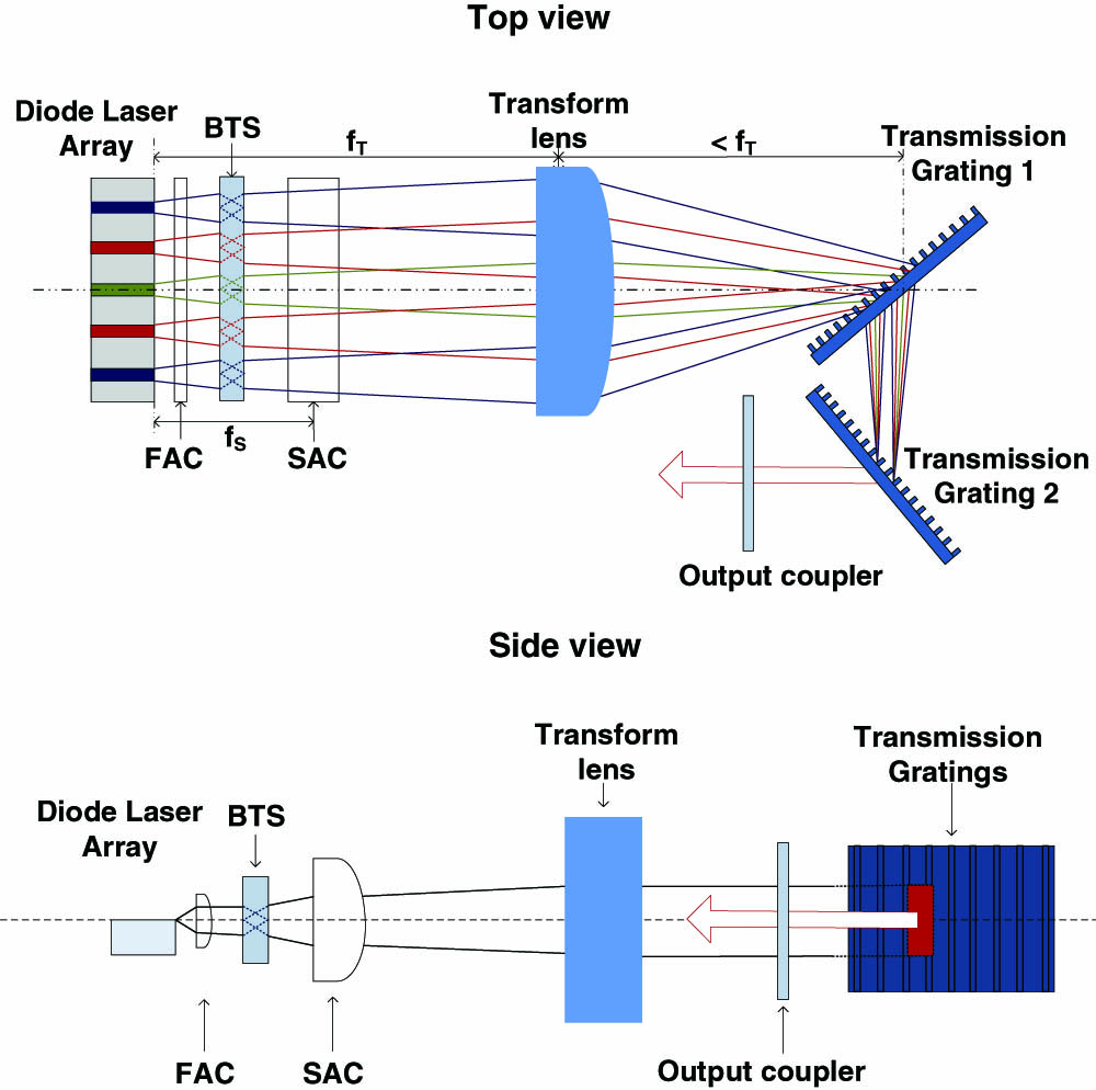
Figure 1.Structure of beam combining.
To narrow down the spectral span, we use two transmission gratings instead of one grating as the diffraction element. Each beam from the laser array has a unique incident angle on the gratings. The back facet of the laser array and the output coupler form a laser cavity, and beams get oscillated in this external cavity. After the beams are diffracted by the grating pair, only beams with a vertical incident angle on the output coupler can be reflected back to the laser emitters and get amplified. Therefore, all the beams are locked at monotonically typical wavelengths and have the same diffraction angle.
The diode-laser array used in this experiment is a common commercial 940 nm CW diode-laser array consisting of 19 emitters. The 19 emitters are placed horizontally and the width of each emitter is 500 μm; the active layer width is 100 μm with a fill factor of 20%. The typical fast-axis divergence angle of a single element with 95% power is 46°, and the slow-axis divergence angle is 9°. In order to decrease the effect of the laser array’s original resonators, the front facets of the laser emitters are antireflection coated.
The fast axis collimator (FAC) is a cylindrical lens that is placed to collimate laser beams in the fast axis. Beams are focused in the vertical direction so the divergence angles in the fast axis reduce to
The BTS is a micro lens array used as beam-shaping element to rotate each single beam 90°. In another words, the fast axis was originally in the vertical direction and became in the horizontal direction after BTS, and contrarily, the slow axis changes oppositely. The beam-combining direction turns from the slow axis to the fast axis. For an individual beam, the beam quality of the fast axis is much better than the slow axis, moreover, the slow axis is also affected by the smile phenomenon. Emitters are able to receive their own feedback more easily and accomplish beam combining when beams are combined on the fast axis.
The purpose of an SAC is similar to the FAC. After having the beams rotated, the slow axis is in the vertical direction, and the SAC is a cylindrical lens that aims to reduce the divergence angle on the slow axis. The focal length of the SAC is 60 mm.
The transform lens is placed between the laser array and the grating pair, and is one focal length away behind the laser array. The transform lens is also a cylindrical lens with a focal length of 300 mm, and it focuses all the beams on the gratings. The beam spots partially overlap on the first grating and completely overlap on the second grating.
The grating pair includes two transmission gratings (1500 lines/mm), and the efficiency of the
The incidence angle of the central beam is a Littrow angle on both the first and the second grating to achieve the highest efficiency. The reflectivity of the output coupler is 10%. In traditional SBC structures, the grating is placed one focal length away from the transform lens to obtain a smallest beam spot on the grating. In double-grating structures, the first grating should be placed slightly less than one focal length away from the transform lens, and the second grating is a little behind the first grating to achieve the smallest beam spot on it.
The process of both traditional SBC and double-grating SBC will be shown as follows to explain how the spectral span can be narrowed to 50% in a double-grating structure.
Figure
![]()
Figure 2.Simplified optical path of a traditional SBC.
The whole spectral span is[
Figure
![]()
Figure 3.Simplified optical path of the double-grating SBC.
As all the beams have the same diffraction angle after the second grating, the differential equation is simplified as follows:
The incident angles on the two gratings are both Littrow angles so that
The calculated spectral span is 7.1 nm. Comparing Eqs. (
Additionally, the spectral span is inversely proportional to the focal length of the transform lens in Eq. (
Figure
![]()
Figure 5.Spectrum of the single-grating SBC laser.
![]()
Figure 4.Spectrum of the double-grating SBC laser.
In addition, the central wavelengths in Figs.
The double-grating SBC and free running output powers are both shown in Fig.
![]()
Figure 6.Output power and efficiency of the double-grating SBC laser, 30.9 W output power, and 70.5% efficiency is demonstrated.
The main loss during the combining process is the reflectivity from all these elements. Any reflectivity may form a subcavity and decreases the combining efficiency; if the optical components were antireflection-coated the efficiency will be higher. On the other hand, on the condition that the loss in the laser cavity is reduced, the reflectivity of the output coupler can also be lowered, and the optical-optical efficiency can also be better.
As it is antireflectivity coated on front facet of the laser array, the free running threshold current increases to 9 A, and is larger than the SBC threshold current of 5 A. When the operating current is near the threshold current, the SBC power may be higher than the free running power.
Figure
![]()
Figure 7.(a) Beam quality after SBC. (b) The output beam spot.
In conclusion, a new method of SBC with a double-grating structure is demonstrated in this Letter, and the spectral span is only a half of that compared with traditional methods; identically, the experimental setup size could be decreased to nearly a half if the spectral span is maintained. We achieve 7.0 nm spectral span output beams by using two transmission gratings as diffractive elements to improve the diffractive ability. The output power of SBC is 30.9 W with a free running combining efficiency of 70.5%, and the electro-optical conversion efficiency is 27.1%. Furthermore, the combining efficiency of the double-grating SBC can be increased remarkably by reducing the loss in the external cavity. Meanwhile, the reflectivity of the output coupler can also be optimized.
With the spectral span narrowed down, we can add more emitters in SBC to take full advantage of the gain range of the diode-laser material and the high diffraction range of the gratings. It provides us a promising method to develop a diode laser with a higher output power and brightness.
References
[1] F. Bachmann. Appl. Surf. Sci., 208, 125(2003).
[2] X. Yang, Y. Yin, X. Li, S. Xu, Y. Xia, J. Yin. Chin. Opt. Lett., 14, 071403(2016).
[3] D. Schröder, D. Lorenzen. Proc. SPIE, 6456, 64560N(2007).
[4] C. C. Cook, T. Y. Fan. Adv. Solid-State Lasers, 26, 163(1999).
[7] J. T. Gopinath, B. Chann, T. Y. Fan, A. Sanchez-Rubio. Opt. Express, 16, 9405(2008).
[8] J. Zhang, H. Peng, X. Fu, Y. Liu, L. Qin, G. Miao, L. Wang. Opt. Express, 21, 3627(2013).
[9] Z. Zhu, L. Gou, M. Jiang, Y. Hui, H. Lei, Q. Li. Opt. Express, 22, 17804(2014).
[10] C. E. Hamilton, S. C. Tidwell, D. Meekhof, J. Seamans, N. Gitkind, D. D. Lowenthal. Proc. SPIE, 5336(2004).
[11] H. Cao, C. Zhou, J. Feng, P. Lv, J. Ma. Appl. Opt., 49, 4108(2010).
[12] S. Wang, C. Zhou, Y. Zhang, H. Ru. Appl. Opt., 45, 2567(2006).
[13] W. Sun, P. Lv, C. Zhou, J. Wu, S. Wang. Chin. Opt. Lett., 11, 070502(2013).
[14] J. Wu, C. Zhou, H. Cao, A. Hu, W. Sun, W. Jia. Chin. Opt. Lett., 11, 060501(2013).
[15] J. Feng, X. Zhang, D. Wu, S. Wu, X. Yuan. Chin. Opt. Lett., 13, S10901(2015).
[16] X. Zhang, F. Gao, J. Feng, K. Zou, B. Xiong, X. Yuan. Chin. Opt. Lett., 12, 030901(2014).

Set citation alerts for the article
Please enter your email address
© Copyright 2018-2021 | Chinese Laser Press. All Rights Reserved 沪ICP备15018463号-20