Abstract
Fiber-optic laser–ultrasound generation is being used in an increasing number of applications, including medical diagnosis, material characterization, and structural health monitoring. However, most currently used fiber-optic ultrasonic transducers allow effective ultrasound generation at only a single location, namely, at the fiber tip, although there have been a few limited proposals for achieving multipoint ultrasound generation along the length of a fiber. Here we present a novel fiber-optic ultrasound transducer that uses the core-offset splicing of fibers to effectively generate ultrasound at multiple locations along the fiber. The proposed laser–ultrasonic transducer can produce a balanced-strength signal between ultrasonic generation points by reasonably controlling the offsets of the fibers. The proposed transducer has other outstanding characteristics, including simple fabrication and low cost.1. INTRODUCTION
Active ultrasonic testing using ultrasonic generation and detection is widely used in medical diagnosis, material characterization, structural health monitoring, and nondestructive evaluation [1–3]. Active ultrasonic methods involve the use of an ultrasonic transducer to project ultrasound signals onto a target structure and an ultrasonic detector to detect structural damage based on the reflected or transmitted signals. In some specific application areas, for example, structural health monitoring of aircraft and buildings, the ultrasonic transducer must be permanently confined within a limited space and shielded from electromagnetic field interference to attain multipoint or distributed ultrasound generation [4]. Traditional piezoelectric transducers (PZTs) are not suitable for this type of permanently embedded, multipoint ultrasound generation because their bulky bodies and electric wiring limit the number of embedded transducers. PZTs are also susceptible to electromagnetic interference, leading to poor data reliability. Fiber-optic laser–ultrasonic transducers have many advantages over PZTs, including smaller size, less weight, immunity to electromagnetic interference, and suitability for use in permanently embedded applications [1,2,4–8]. These advantages make this type of transducer a promising candidate for use in multipoint laser–ultrasound generation along a fiber, a technique with important potential in applications involving distributed ultrasonic sensing such as real-time structural health monitoring [4].
A number of fiber-optic laser–ultrasonic transducers based on various photoacoustic conversion materials—including metal films [6], graphite and epoxy resin mixtures [9], gold nanocomposite and poly-dimethylsiloxane (PDMS) mixtures [10,11], and carbon nanotube and PDMS mixtures [12]—have been proposed and evaluated. However, most of these transducers can generate ultrasound waves at only a single point—the fiber tip. A few attempts to obtain multipoint laser–ultrasound generation along the length of a fiber have been reported, but these have had limited success. The challenge so far has been to find a means to effectively extract the light signal from specific locations on the optical fiber sidewall. For example, multipoint laser–ultrasound generation has been achieved over a span of multimode fiber by directly polishing the fiber cladding layers all the way into the core and replacing them with absorption coatings at selected locations [4]. However, it is not easy to precisely control laser energy extracted from each location on the sidewall, leading to an imbalance in the ultrasound wave strength generation between points and, therefore, a limitation on the maximum number of obtained laser–ultrasound transducers. Furthermore, the fiber-polishing process requires specialized equipment, which is not cost-effective. Another alternative involves coupling light in a single-mode fiber (SMF) from the core mode into the ghost mode using a series of tilted fiber Bragg gratings with different wavelengths to achieve multipoint ultrasonic generation [13]. However, the ultrasonic amplitude obtained is relatively low, and the system requires a scanning laser as a pulsed source, which also raises the cost. Finally, the number of transducers that can be supported in this method is limited by the laser operating bandwidth and the linewidths of the gratings.
In this paper, we propose and demonstrate a novel multipoint fiber-optic laser–ultrasound generation method based on the core-offset splicing of SMFs. The proposed fiber core-offset structure (FCOS) can effectively couple light from the core mode into the cladding modes to enable ultrasonic generation. Multipoint laser–ultrasonic generation can be easily achieved by connecting multiple FCOSs in a fiber link, and the mode-coupling ratio of the FCOSs can be controlled by adjusting the core-offset displacement size, leading to balanced-strength signal generation among the ultrasonic transducers. This performance capability enables an increase in the number of transducers in the system and enhances ultrasonic signal detection and demodulation. Using this method, we developed a five-point laser–ultrasound transducer with balanced signal strength along a fiber by fabricating five FCOSs with different displacement sizes. Using a pulsed laser (1550.2 nm center wavelength, 5 ns pulse width, and 3 kHz repetition frequency) amplified by a high-power erbium-doped fiber amplifier (EDFA, 120 mW average output power), we produced a five-point laser–ultrasound transducer along a fiber with high, balanced ultrasonic signal strength and amplitudes of 482, 526, 480, 510, and 466 mV. Only standard fiber instruments and materials such as a fusion splicer, a cleaver, and an SMF are needed to fabricate the FCOS, enabling simple, cost-effective fabrication.
Sign up for Photonics Research TOC. Get the latest issue of Photonics Research delivered right to you!Sign up now
2. WORKING PRINCIPLE AND FABRICATION
The multipoint laser-generation system, shown schematically in Fig. 1(a), is based on the core-offset splicing of SMFs [14–16]. In the system, a pulsed laser amplified by an EDFA is used to supply laser energy, and several FCOS units connected via a fiber link serve as multipoint laser–ultrasound transducers. Each FCOS is constructed by fusion-splicing two cleaved fibers at a specific lateral displacement, as shown in Fig. 1(b), in which it is seen that the light signal propagates steadily in the SMF as the fundamental core mode prior to its arrival at the FCOS. The core-offset structure in the fibers breaks the single-mode transmission condition, allowing a portion of the light signal to couple into the cladding modes from the core mode. The energy of the cladding modes is absorbed by ultrasonic-generating materials that replace part of the fiber cladding and transformed via the thermoelastic effect into an ultrasonic wave at the current core-offset point. The remaining energy in the core mode continues to steadily propagate in the fiber, supporting ultrasound generation in the downstream FCOSs and thereby enabling multipoint laser–ultrasound generation.
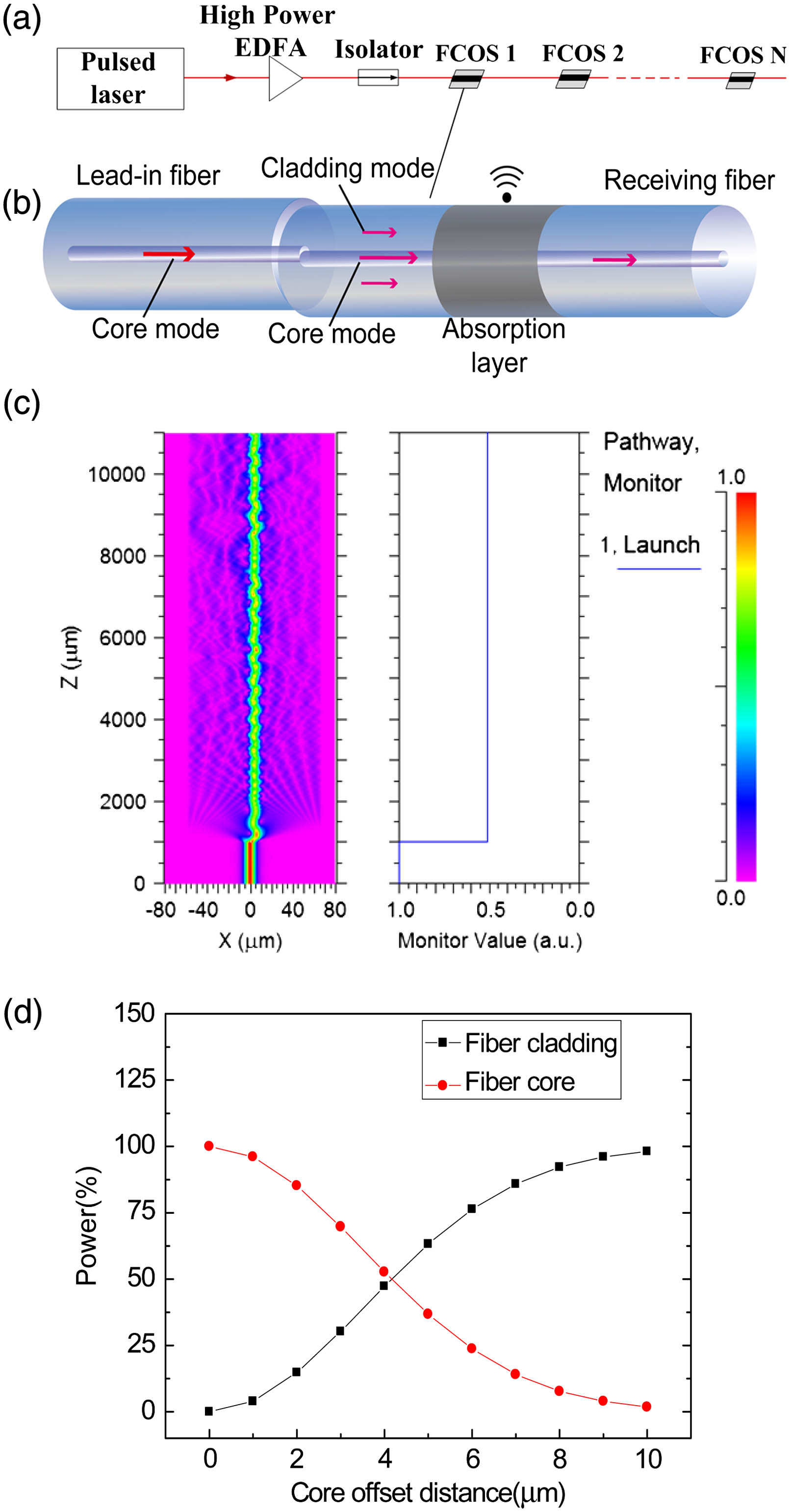
Figure 1.Conceptual illustration of multipoint fiber-optic laser–ultrasound generation. (a) Schematic of the proposed system. (b) Structural illustration of an FCOS. (c) Transmission light field distribution of an FCOS with a 4 μm offset along the axis. (d) Relationship curve between the energy ratio coupled from the core mode to the cladding modes and the dislocation offset of the FCOS.
To investigate the evolution of the light field distribution through the fiber core-offset region, we conducted a theoretical analysis using the finite element beam propagation method. To simulate beam propagation in an optical fiber, we applied the commercial software Rsoft with the Beam PROP module. SMF parameters from Corning SMF-28 were used in the simulation, with the diameter and refractive index of the fiber core set to 8.3 μm and 1.45213, respectively, and the diameter and refractive index of the cladding set to 125 μm and 1.44692, respectively. The background was set to air, and the FCOS was modeled by splicing two uncoated SMFs with a 4 μm offset along the axis. The core-offset point was set behind a 1000-μm-long lead-in SMF. Fundamental excitation with a wavelength of 1550 nm was assumed, and the mesh size was set to .
Figure 1(c) shows the energy evolution in core mode (right) and the light field distribution over the entire fiber (left) with light passing through the FCOS. The tiny core-offset dislocation of 4 μm results in negligible reflection of light from the fiber cores at the core-offset point. However, the destruction of the structural symmetry of the fiber at the core-offset region induces partial coupling of the core mode into the cladding modes. As seen in Fig. 1(c left), the fundamental mode (typically LP01 in SMF), in which the power is normalized, steadily propagates up to 1000 μm in the lead-in fiber core until it reaches the core-offset point, following which the core mode is rapidly coupled into the forward scattering cladding modes at the core-offset region. As shown in Fig. 1(c left), total inner light reflection occurs on the cladding–air plane 800 μm behind the core-offset point, enabling the cladding modes to provide forward, lossless propagation in the fiber. Small perturbations occur in the energy in the fiber core region as a direct result of interference between the core mode and the cladding modes. However, the energy in the core mode is maintained at a fixed level and propagates forward steadily [see Fig. 1(c right)] and can therefore be used to feed subsequent fiber core-offset units. As shown by the simulation, 50% of the total energy remains in the core mode downstream from the core-offset unit, indicating that 50% of the energy is coupled into the cladding modes at a fiber core dislocation of 4 μm.
We also investigated the correlation between mode-coupling efficiency and degree of FCOS dislocation by changing the dislocation from 0 to 10 μm in steps of 1 μm in the simulation. A quantitative relationship curve between dislocation size and coupling ratio is plotted in Fig. 1(d), showing that increasing the dislocation of the two fiber cores increases the core energy that can be coupled into the cladding modes (and decreases the energy remaining in the core mode). This result suggests that the mode-coupling ratio of the FCOS units can be varied by adjusting the dislocation offset of the fiber cores during the fiber-splicing process. If the FCOS units are set with specific coupling ratios according to the mode-coupling ratio in series from small to large over one fiber link, equal cladding mode energy can be coupled from each fiber core-offset unit to further guarantee ultrasonic signal generation with balanced amplitude at each core-offset ultrasonic transducer, which in turn improves the energy utilization of the system light source and increases the number of ultrasonic transducers that can be supported by one fiber link system.
Simulations such as those summarized in Fig. 1(d) can help in guiding experimental efforts to obtain the required coupling ratio based on the dislocation offset, making it possible to quantitatively control the optical energy absorbed by the photoacoustic conversion materials for balanced-strength ultrasound generation.
To achieve multipoint ultrasonic generation with balanced strength, the energy of the cladding modes used for generating ultrasound must be experimentally controlled at each point. For example, a multipoint ultrasonic transducer that can achieve five-point ultrasound excitation with balanced ultrasonic intensity, as described in our experimental section, required setting the individual FCOS unit coupling ratios to 20%, 25%, 33%, 50%, and 100% in order down the transducer chain. Each FCOS unit was fabricated by splicing two cleaved SMFs (Corning SMF-28) using a fiber splicer (Fujikura FSM-80s) in manual mode. The two SMFs were first placed in the splicer and aligned using the splicer’s stepper motors. Then the fibers were set at a slight lateral deviation along the axis by adjusting the stepper motors prior to electrode discharge. To compensate for the lack of motor precision in the process and accurately achieve specific mode-coupling ratios, the other ends of the lead-in and receiving fibers were connected to a narrow linewidth laser and a power meter, respectively, to monitor the power fluctuation of the core mode as the dislocation size was adjusted by the stepper motors. In this way, the mode-coupling ratio can be accurately evaluated by comparing the original laser power with the monitored power. Finally, after obtaining the specific mode-coupling ratio, the FCOS was fabricated by splicing the two fibers while discharging the electrodes. Note that the slight deformation of fiber occurring during electrode discharge caused the final coupling ratio to deviate slightly from the predetermined value. The final experimental coupling coefficients of the five fiber core-offset units were 20.2%, 28.22%, 31%, 50.3%, and 99.86%, respectively. Microphotos of each taken in the and directions by the splicer are shown in Fig. 2, clearly demonstrating that increasing the dislocation of the fiber cores increases the obtainable coupling ratio, in close agreement with the preceding theoretical analysis. The fabricated FCOSs were connected in series over a fiber link in increasing order of coupling ratio, resulting in energy coupling to the cladding modes of 20.2%, 22.52%, 17.76%, 19.88%, and 19.16%, respectively, at the five core-offset points.

Figure 2.Core-offset units with varying dislocation sizes photographed by the fiber fusion splicer with coupling ratios of 20.2%, 28.22%, 31%, 50.3%, and 99.86%, respectively.
3. EXPERIMENTAL RESULTS AND DISCUSSION
The proposed method for multipoint fiber-optic laser–ultrasound generation along a fiber was demonstrated using the experimental setup schematically shown in Fig. 3. The five FCOSs fabricated in the process described in the previous section were connected via the fiber link in increasing order of dislocation offset. The length of fiber between each pair of FCOS was approximately 1 m. A pulsed laser (Maxphotonics: VLSS-1550-M-PL-MP) with a central wavelength of 1550 nm, a 3 kHz repetition rate, and a 5 ns pulse width was used as a seed laser source and was amplified using a high-power EDFA (Maxphotonics: MFAS-1550-B-HP-PL), with a maximum output average power of more than 1 W. To prevent the backward reflection of light, a high-power fiber isolator was inserted between the EDFA and the FCOS chain. The power utilization ratio of the cladding modes was improved by reducing the diameter of the fiber cladding around the core-offset splicing region from 125 to 50 μm through wet chemical etching using a 40% hydrofluoric acid (HF) solution (it is well established that decreasing the cladding diameter to tens of micrometers will not affect the transmissivity of the core mode). Micropictures of a typical fiber core-offset region before and after HF etching are shown in Fig. 3(b). A mixture of graphite powder () and epoxy (Duralco: 4460) resin was used as the laser-responsive, ultrasonound-generating material, which was used to bury the etched region of the core-offset fibers into a 200-μm-deep slot premachined onto a aluminum plate prior to solidification at a high temperature (120°C) for 4 h, as shown in Fig. 3(c). The cured graphite/epoxy mixture also serves as a highly absorptive material with a large thermal expansion coefficient for efficient laser–ultrasound generation. It is noted that due to the small lateral displacement (several micrometers), the mechanical strength of the typical FCOS is approximately equal to spliced SMFs. Meanwhile, the etched region of the FCOS is protected by the cured acousto-optic material: epoxy resin and graphite. These characteristics make the FCOS very robust in real applications. The generated ultrasound signal was detected using a PZT ultrasonic sensor (OLYMPUS: V120-RB) with a resonant frequency of 7.5 MHz mounted underneath the buried fiber on the opposite side of the aluminum plate. The detected ultrasound signal was converted into an electrical signal and then amplified by 60 dB with an electrical amplifier (OLYMPUS: 5660C) before finally being recorded in an oscilloscope (Tektronix: MDO3104).
Figure 3.Experimental demonstration. (a) Schematic of the experimental setup. (b) Pictures of core-offset fibers before and after chemical etching. (c) Prepared FCOS-based transducer.
Prior to ultrasound signal detection, the characteristics of the laser source were studied by measuring the spectrum of the pulse laser after it passed through the EDFA using an optical spectrum analyzer (OSA, YOKOGAWA: AQ6370C), as shown in Fig. 4(a). The post-EDFA laser pulse signal was received by a photoelectric detector (PD, THORLABS, PDB410C) and recorded by an oscilloscope to produce the signals shown in Figs. 4(b) and 4(c). The spectral analyzer results in Fig. 4(a) indicate a central laser wavelength of 1550.2 nm, a 3 dB linewidth of 0.12 nm, and a wide base (1.12 nm) The pulse duration is 5 ns, and the repetition frequency is 3 kHz, as seen from Figs. 4(b) and 4(c), respectively. The average EDFA output power used in the experiments was tuned to 120 mW, corresponding to a calculated per-pulse energy of 0.04 mJ.
Figure 4.Laser characteristics and generated ultrasound signal. (a) Laser spectrum after passing through an EDFA. (b) Single laser pulse measured post-EDFA. (c) Laser pulse train with a 3 kHz repetition rate post-EDFA. (d) Narrow ultrasonic pulse train with a repetition rate of 3 kHz generated by the first core-offset unit. (e) Enlarged view of the ultrasonic pulse and (f) Fourier transform of the detected ultrasonic pulse.
Based on the coupling ratios of the FCOS units, the per-laser pulse energy coupled into the cladding modes at each FCOS is about 0.008 mJ. The energy in the cladding modes is absorbed by the epoxy and graphite mixture and transformed into heat, which, based on the epoxy’s thermoelastic properties, is then partially converted into an ultrasound wave at each FCOS unit. For example, a series of narrow ultrasonic pulses with a repetition frequency of 3 kHz generated from the first FCOS is shown in Fig. 4(d). This ultrasonic pulse train has the same repetition pattern as the laser source, proving that the ultrasonic signal is excited by the seed laser. A detailed view of an ultrasonic pulse is shown in Fig. 4(e). Its Fourier transform, shown in Fig. 4(f), indicates that the generated ultrasound had a broad and relatively flat spectrum below 20 MHz.
To demonstrate the system’s multipoint laser–ultrasound generation capability, we examined the ultrasound signals generated by each FCOS unit. Ultrasonic pulse trains with a 3 kHz repetition frequency were detected from all five FCOS transducers. Detailed views of the respective ultrasonic pulses and their Fourier transforms are shown in Fig. 5; it is seen from Figs. 5(a)–5(e) that the peak-to-peak values of the ultrasonic signals are essentially consistent at 482, 526, 480, 510, and 466 mV, respectively. As noted previously, the energy coupled to the cladding at the five core-offset points is 20.2%, 22.52%, 17.76%, 19.88%, and 19.16% of the total energy. The slight inconsistencies among the coupling ratios and ultrasonic amplitudes of the units could be a result of the different ultrasound absorbing levels of the varying-thickness epoxy and graphite mixtures. All of the FCOS units’ ultrasonic signals show broad and relatively flat spectra below 20 MHz, as shown in Figs. 5(f)–5(j). The wideband ultrasonic generation of the proposed system make it more competitive in the broadband ultrasound applications, such as photoacoustic study of the first layers of irradiated tissue [1], high resolution vascular tissue imaging [2], and clinical diagnosis [6], than the traditional PZT sources.
Figure 5.Enlarged view of ultrasonic pulse signals generated from five fiber core-offset units and their respective Fourier transforms.
These experimental results suggest that the proposed method can effectively support multipoint laser–ultrasound generation with balanced signal strength along a fiber. The ability of the system to maintain balanced signal strength is obviously important in ensuring that the laser energy is not consumed completely by the first few upstream transducers, allowing the downstream transducers to receive equal amounts of laser energy for effective laser–ultrasound generation and increasing the potential number of ultrasonic transducers in the system.
The proposed ultrasound generator can be regarded as a point or line source. It might be not easy to direct or focus to a certain location. However, even given this, based on the performances of the proposed system we still have several methods to improve the strength of the ultrasound wave on the aimed location, for example, improving the EDFA output power, increasing the number of the generators around the aimed location, and laying the ultrasound generators at closer distance to the aimed region.
We also experimentally studied the relationship between ultrasonic signal strength and diameter of the fiber cladding of the fiber core-offset region. To do this, we fabricated seven FCOSs with the same coupling ratio of 50%, but varied their cladding diameters from 32 to 98 μm by altering the chemical etching times. We individually tested the respective excited ultrasonic signals under the same input seed laser condition used previously except with the average output power of the EDFA reduced by , reducing the energy coupled to the cladding at each FCOS point to 0.0032 mJ. The density of the optical fiber decreased as the diameter increased. For instance, at a fiber cladding diameter of 98 μm, a 65 mV peak-to-peak amplitude ultrasonic wave was detected. The highest peak-to-peak signal amplitude of 210 mV was achieved when the fiber cladding diameter was decreased to 32 μm. As seen from Fig. 6, as the etched fiber cladding diameter became smaller, the ultrasonic signal strength increased. These results suggest that decreasing the cladding diameter can improve the light energy utilization efficiency and increase the number of effective ultrasonic transducers in the system.
Figure 6.Correlation between diameter of core-offset region and ultrasonic intensity.
There are mainly two factors determining upon the maximum of the distributed points of the proposed system. The first one is the minimum of mode-coupling ratio provided by the FCOS, because that relates to the amount of FCOSs coupling equal energy of the cladding mode in the system. As we discussed previously, the mode-coupling ratio is determined by the dislocation size of the FCOS. While the dislocation size of the FCOS is directly determined by the step size of the stepper motor of the splicer. In our experiments, the fusion splicer (model: Fujikura 80S) is used to fabricate the FCOS, which has a random minimum of the step size between 0.1 and 1 μm for single adjustment of the motor in experiments, leading to the minimum of mode-coupling ratio of FCOS between 0.4% and 4%. Thus, theoretically, the maximum of the balanced ultrasound generation points is more than 25 by the present experimental instruments.
The second factor is the total laser energy level delivered by the fiber link of the proposed system. Currently, five ultrasonic transducers with a balanced peak-to-peak strength around 500 mV have experimentally been demonstrated by 120 mW average output power of the EDFA. Obviously, improving the average output power of EDFA can increase the number of the ultrasonic excitation point. The maximum average output power of the EDFA can reach 1 W, which means there is an 8.3-times improvement space compared with the current experimental results. Assuming that the accuracy of the step size of the stepper motor of the fusion splicer is fine enough, 41 points can be achieved with guarantee of 500 mV peak-to-peak value.
Therefore, under the current experimental conditions, the most important limiting factor is the minimum of the mode-coupling ratio of FCOS. Theoretically more than 25 balanced generation points can be achieved by the present experimental instruments. If the accuracy of the step size of the stepper motor of the fusion splicer is fine enough, the maximum of the generation points can be further improved by several techniques, such as increasing the average output power of the EDFA, replacing the SMF with multimode fiber with higher energy transfer capability, and decreasing the cladding diameter of the core-offset region.
4. CONCLUSION
In this work, we demonstrated a smart multipoint fiber-optic laser–ultrasound transducer based on the splicing of core-offset fibers. This FCOS allows light in the fiber core to be conveniently and effectively tapped from the sidewall of the fiber in a controllable manner, enabling multipoint laser–ultrasonic generation with balanced signal strength. In several experiments, we demonstrated the functionality of a five-point laser–ultrasonic transducer system with a stable ultrasonic signal amplitude of approximately 500 mV. Among other applications, the proposed method could be used in all-fiber embedded ultrasonic structural health monitoring testing systems.
References
[1] E. Biagi, L. Masotti, M. Pieraccini. Fiber optic photoacoustic device: high efficiency and wide bandwidth ultrasonic source. Proceedings of IEEE Instrumentation and Measurement Technology Conference (IMTC), 2, 948-952(1998).
[2] R. J. Colchester, E. Z. Zhang, C. A. Mosse, P. C. Breard. Broadband miniature optical ultrasound probe for high resolution vascular tissue imaging. Biomed. Opt. Express, 6, 1502-1511(2015).
[3] B. Lin, V. Giurgiutiu. Development of optical equipment for ultrasonic guided wave structural health monitoring. Proc. SPIE, 9062, 90620R(2014).
[4] V. Kochergin, K. Flanagan, Z. Shi, M. Pedrick, B. Baldwin, T. Plaisted, B. Yellampalle, E. Kochergin, L. Vicari. All-fiber optic ultrasonic structural health monitoring system. Proc. SPIE, 7292, 72923D(2009).
[5] P. A. Fomitchov, A. K. Kromine, S. Krishnaswamy. Photoacoustic probes for nondestructive testing and biomedical applications. Appl. Opt., 41, 4451-4459(2002).
[6] E. Biagi, M. Brenci, S. Fontani, L. Masotti, M. Pieraccini. Photoacoustic generation: optical fiber ultrasonic sources for non-destructive evaluation and clinical diagnosis. Opt. Rev., 4, 481-483(1997).
[7] L. Belsito, E. Vannacci, F. Mancarella, M. Ferri, G. P. Veronese, E. Biagi, A. Roncaglia. Fabrication of fiber-optic broadband ultrasound emitters by micro-opto-mechanical technology. J. Micromech. Microeng., 24, 085003(2014).
[8] C. Hu, Z. Yu, A. Wang. An all fiber-optic multi-parameter structure health monitoring system. Opt. Express, 24, 20287-20296(2016).
[9] E. Biagi, F. Margheri, D. Menichelli. Efficient laser-ultrasound generation by using heavily absorbing films as targets. T. Ultarson. Ferr., 48, 1669-1680(2001).
[10] X. Zou, N. Wu, Y. Tian, X. Wang. Broadband miniature fiber optic ultrasound generator. Opt. Express, 22, 18119-18127(2014).
[11] N. Wu, Y. Tian, X. Zou, X. Wang. Fiber optic photoacoustic ultrasound generator based on gold nanocomposite. Proc. SPIE, 8694, 86940Q(2013).
[12] H. W. Baac, J. G. Ok, A. Maxwell, K. T. Lee, Y. C. Chen, A. J. Hart, L. J. Guo. Carbon-nanotube optoacoustic lens for focused ultrasound generation and high-precision targeted. Sci. Rep., 2, 989(2012).
[13] J. J. Tian, Q. Zhang, M. Han. Distributed fiber-optic laser-ultrasound generation based on ghost-mode of tilted fiber Bragg gratings. Opt. Express, 21, 6109-6114(2013).
[14] Z. B. Tian, S. S. H. Yam. In-line single-mode optical fiber interferometric refractive index sensors. J. Lightwave Technol., 27, 2296-2306(2009).
[15] G. Yin, S. Q. Lou, H. Zou. Refractive index sensor with asymmetrical fiber Mach–Zehnder interferometer based on concatenating single-mode abrupt taper and core-offset section. Opt. Laser Technol., 45, 294-300(2013).
[16] L. Mao, P. Lu, Z. Lao, D. Liu, J. Zhang. Highly sensitive curvature sensor based on single-mode fiber using core-offset splicing. Opt. Laser Technol., 57, 39-43(2014).

