We propose and demonstrate a novel single fiber optical tweezer based on a graded-index multimode fiber (GIMMF), which works with a free length GIMMF (). We achieve a three-dimensional stable trap of yeast cells by using the GIMMF optical tweezers. Compared with the single-mode fiber optical tweezers, the GIMMF optical tweezers possess large optical trapping forces. Owing to the freedom of the GIMMF length, the fabrication of the GIMMF optical tweezers is simple, repeatable, and highly efficient. The GIMMF tweezers have the penitential to become a new member of the single fiber optical tweezers family and have a wide range of applications in the medical and biological cytology fields.
Since optical tweezers were proposed by Ashkin et al. in 1986[1], optical tweezers have been widely used for the operation of micro- and nano-sized particles. Optical tweezers provide the trapping force for the micromanipulation of biological cells and have a wide range of applications in the biological, physical, chemical, and other fields[2–11]. The optical tweezers can be divided into two categories, one is the traditional optical tweezers based on high NA microscope objectives, and another one is the novel optical tweezers based on optical fibers. Compared with traditional optical tweezers, which are bulky, expensive, and complex, the fiber optical tweezers are simple, low-cost, and convenient for manipulation. From multiple fiber optical tweezers[3] to single fiber optical tweezers[12–17], there have developed a variety of fiber-based optical tweezers. Those fiber optical tweezers have different functionalities, but have one thing in common, they all employ single mode fibers (SMFs). In fact, besides the SMFs, the multimode fibers could also be used as optical trapping probes. Gong et al.[18–20] have performed optical trapping based on a graded-index multimode fiber (GIMMF), which has the longer trapping distance and larger gradient force. However, it needs to satisfy a harsh condition to achieve optical trapping: the length of the GIMMF should be precisely controlled. Therefore, it is difficult to process and fabricate the fiber probe for optical tweezers based on the GIMMF. In order to solve this problem, we propose and demonstrate a single fiber optical tweezer based on a GIMMF, which can work with a free length GIMMF.
According to the Ref. [21], when the laser beam propagates in a multimode fiber, most of the laser powers concentrate in the center of the fiber core after the laser beam propagates a long distance of . In other words, after a long distance transmission in a GIMMF, the laser power distribution is in a stable state, being centralized in the fiber core. The equivalent mode field diameter of the GIMMF is larger than that of the SMF with the same laser wavelength. It indicates that the optical trapping force will generate if the tip of the GIMMF is fabricated to be a suitable shape. In addition, the optical trapping force generated from the GIMMF probe is larger than that generated from the SMF with the same shaped fiber tip.
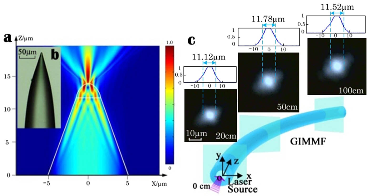
The diameters of the fiber core and cladding of the GIMMF used in our experiment are 62.5 and 125 μm, respectively. The refractive index profile of the GIMMF can be expressed as where is the maximum of the refractive index at , is the core radius, and is the factor that determines the index profile. The refractive index difference between the core and the cladding is , where , , and . The fiber heating fused and tapered method is used to fabricate the fiber tip. The solid angle of the fiber tip is 33° [see Fig. 1(b)]. We employ the Beam Propagation Method using BeamPROP software, which is part of the RSoft software to simulate the output light field from the GIMMF tip [see Fig. 1(a)]. The output light field from the GIMMF probe converges near the fiber tip with a large gradient. The simulated condition contains the laser source wavelength of 980 nm. The background index is . The equivalent incident mode field diameter of the 980 nm laser beam for the GIMMF probe is about 10 μm, which is obtained from the experimental results [see Fig. 1(c)]. We measure the mode field diameters of the output light fields from different beam propagating distances, and the results show that the mode field diameters in different positions stay unchanged when the length of the GIMMF is larger than 30 cm.
Sign up for Chinese Optics Letters TOC. Get the latest issue of Chinese Optics Letters delivered right to you!Sign up now
Figure 1.(a) Simulated results of the output light field distribution. (b) Image of the tapered-shaped GIMMF tip fabricated by using the fiber heating fused and tapered method. (c) Near-field images of the GIMMF output recorded at the pump wavelength of 980 nm and the corresponding beam profiles (normalized intensity). When the length of GIMMF is 20, 50, and 100 cm, the full width at half-maximum intesnsity diameters of the beam are 11.12, 11.78, and 11.53 μm.
The time domain finite difference (FDTD) method is used to simulate and calculate the optical trapping forces introduced by the GIMMF probe[4]. We build a two-dimensional (2D) model with a TM mode 980 nm laser source by using the FullWAVE module of the commercial RSoft software. The , , and components of the output light field are obtained to calculate the transverse and axial trapping forces.
Figure 2(a) provides the calculated results of the axial trapping forces introduced by the GIMMF probe. We define that the positive direction of the axis is along the laser beam propagating direction. Thus, the negative value of the optical trapping forces indicate there exists pulling forces exerting on the microparticle. We simulate and calculate the optical trapping forces introduced by the GIMMF probe with solid tapered angles of 31°, 32°, 33°, 34°, and 35°, and the SMF probe with the solid tapered angle of 33°. The results show that the optical trapping forces generated from different fiber probes have a similar trend. In addition, for the microparticles whose refractive index is 1.4 and diameter is 5 μm, the GIMMF probe with the 33° solid angle is optimal. The optical trapping forces introduced by the GIMMF probe with the 33° solid angle is much larger than that introduced by the SMF probe with the 33° solid angle.
Figure 2.(a) Simulated results of the axial optical trapping force introduced by the GIMMF probes with different solid angles. (b) The simulated results of the transverse optical trapping force introduced by the GIMMF probes with different solid angles ( coordinate of the microparticle is 2.5 μm). The diameter of the trapped microparticle is 5 μm, and the refractive index of the microparticle is 1.4.
Figure 2(b) provides the calculated results of the transverse trapping forces. The negative value of the optical trapping forces means the output laser beam will drag the microparticle towards the fiber main axis along the transverse direction. The net optical forces are zero when , which indicates that the microparticle will be in the equilibrium state along the transverse direction when . In other words, the microparticle will be trapped on the axis. Being similar to the results of axial trapping forces, the transverse forces introduced by the GIMMF probe with the solid angle of 33° is optimal. The transverse trapping force generated from the GIMMF probe with the 33° solid angle is 5 times larger than the transverse trapping force generated from the SMF probe with the 33° solid angle.
Figure 3 shows the experimental setup of the sketch diagram the optical tweezers based on the GIMMF. A 980 nm laser pumping source with the power adjusting range of 0–300 mW is used. A 1:99 fiber coupler is used to monitor the incident laser power in real-time. The fiber probe is mounted on a three-dimensional (3D) micromanipulator platform, and the position of the fiber probe is accurately adjusted by the microcontroller. The target microparticle is the yeast cell in the experiment. The diameter of the yeast is 5 μm, and the refractive index of the yeast is 1.4.
Figure 3.Experimental setup of the optical tweezers based on the GIMMF with a free length. PC, personal computer.
Figure 4(a) provides a sequence of video screenshots at different times when we employ the GIMMF probe to trap a yeast cell. We turn on the power of the laser source at , and we achieve the stable trap of the yeast cell within the 0.05 s. According to Fig. 4(a), when the yeast cell passes through the effective area of the GIMMF probe, it will be absorbed and trapped by the GIMMF probe. Similarly, the video screenshots in Fig. 4(b) show the releasing process of the optical trap. We turn off the power of the laser source at , and then the yeast cell moves away from the fiber tip within the 0.05 s.
Figure 4.Video screenshots of a yeast cell (a) trapped and (b) released by the GIMMF probe at different times.
Figure 5 shows the experiment manipulation results. By using the 3D micromanipulator platform, we mount the GIMMF tip on the microscope. We achieve the 3D stable trap of a yeast cell when we turn on the laser source [see Fig. 5(a)]. In order to show the stable trap in a 3D space, we move the fiber probe along the transverse direction, moving upward and downward in the view field of the CCD [see Figs. 5(a) and 5(b)]. Similarly, we move the fiber probe along the axial direction, moving forward and backward in the view field of the CCD [see Figs. 5(b) and 5(d)]. Here, the stable trap power of the 980 nm laser source is 9.12 mW. In addition, for the GIMMF probe and SMF probe with the same fiber tip shape, the minimum trapping power of the GIMMF probe is 8.20 mW, which is one-fourth of the minimum trapping power of a normal SMF probe (). However, we know that this minimum trapping power ratio is also related to the shape of the fiber probe tip. Consequently, the trapping power of the GIMMF probe is lower than the SMF probe, which helps reduce the heating effect produced by the laser power.
Figure 5.(a) Image of a yeast cell trapped by the GIMMF optical tweezers; (b) image of the GIMMF probe moving along the transverse direction with a shift of ; (c) image of the GIMMF probe to show the definition of the coordinate system; (d) image of the GIMMF probe moving along the axial direction with a shift of .
In conclusion, we propose and demonstrate a novel single fiber optical tweezer based on a free length of GIMMF. The simulated results show that the trapping force introduced by the GIMMF optical tweezers is about 5 times larger than that generated from the SMF tweezers with the same solid angle. The experimental results show that the GIMMF optical tweezers can trap the yeast cell steadily in a 3D space.
The structure of the GIMMF optical tweezers is simple, and the cost of the GIMMF optical tweezers is low. In addition, owning to the freedom of the GIMMF length, the manufacturing process of the GIMMF optical tweezers is easy. Therefore, the GIMMF optical tweezers have the potential to be a new implement for the medical and biological cytology fields.