A model that considers both thermal expansion and thermo-optical effects is developed to investigate the transmission variation of optical coatings when they are exposed to an intense laser beam. Our results indicate that a higher gradient of the transmission spectrum curve at a certain wavelength leads to a more evident variation of the coating transmission. Three customized multilayer coatings with different transmission spectra are used to measure the transmitted power under the irradiation of a 1080 nm continuous-fiber laser. Excellent agreement is found between the experimental result and the theoretical prediction. Our result is helpful for the improvement of such devices in the application of high-power laser systems.
In the active field of laser interaction with optical coatings, the damaging behaviors of the components have been given much attention[1–4]. However, before reaching the damage point, some interesting physics happen, such as the variation of the coating transmission[5]. When the materials of a coating are excited by the incident intense laser, the dielectric function can be changed, and the transmission spectrum of the devices is influenced[3,6]. This should be a dynamic process.
During the coating design and manufacture processes, the stability of the transmission spectrum is an important factor[7,8]. Under the condition of a small signal, the transmission spectrum is mainly determined by the materials and the coating system. If the refractive indices of the coating materials are changed under the irradiation of the laser, a shift in the transmission curve may happen, which, consequently, influences the working performance of the device. For example, let us consider a narrow-band filter[9,10]: a little shift in the transmission and/or reflection curve will change the central wavelength of the pass and/or stop band[8]. And when a coating device is used for the power sampling in the monitoring of the laser power arriving at the target surface, such a phenomenon is detrimental, and should be avoided. Insight into this problem can with understanding the mechanism and finding a way to overcome this disadvantage.
The laser-matter interactions include photo-ionization and macroscopic thermal effects. Photo-ionization is often investigated in the case of femtosecond laser irradiation, in which the real and imaginary parts of the refractive index can both be altered[6,11]. And, generally, the thermal effect is more universal during laser illumination[12–14]. In Ref. [5], we used a high-repetition femtosecond laser to irradiate a bandpass optical filter, and a preliminary study of the laser-induced transmission variation is available. We demonstrated that the transmission increase in the bandpass filter under the irradiation of high-repetition femtosecond pulses was mainly induced by the heating effects, which occurred due to the relatively moderate laser intensity. Here, we will provide more in-depth understandings of such observations and, at the same time, verify the analysis in Ref. [5]. First, on the basis of the optical length of the coating layer, the model of the equivalent refractive index changing as a function of the magnitude of the temperature rising is derived. Then, an experiment using a single lateral mode, 1080 nm, high-power fiber laser to irradiate three customized coating samples is carried out.
Sign up for Chinese Optics Letters TOC. Get the latest issue of Chinese Optics Letters delivered right to you!Sign up now
For the oxide coating materials, e.g., , the refractive index and the mass density have the empirical approximate relation , where is the mass density, and is a constant[15,16]. When exposed to an intense laser, thermal expansion occurs in the multi-layered structure, which results in a decrease in the mass density and an increase in the physical thickness. Consequently, the refractive index reduces, and the optical length of the coating layer is modified simultaneously. The thermo-optical coefficient can also produce a change in the refractive index.
If the magnitude of temperature rising is , the new physical thickness and mass density can be written as where and represent the expansion coefficient and the original physical thickness, respectively. It should be noted that Eq. (2) is based on the assumption that the thermal expansion of the coating materials is free in all directions. From the approximate relation mentioned above, the refractive index after expansion is The value of is small, so Eq. (3) can be expanded through the Taylor expansion and simplified as[17]The contribution of the thermo-optical effect to the variation of the refractive index can be expressed as From Eqs. (4) and (5), we can obtain the final expression of the refractive index through linear superposition. It can be written as Thus, the new optical length of the coating layer after thermal expansion is We should note that an expansion and a series of simplification methods are used in the treatment of Eq. (7).
In the process of a coating being heated up by a laser, the alterations in the refractive index and the coating thickness are simultaneous. For the optical length at a certain wavelength, these two alterations can essentially be treated equally. That is, the change in the coating thickness can also be regarded as a change in the refractive index at a certain wavelength. Therefore, from Eq. (7), the equivalent variation of the refractive index is At a particular wavelength, if the scope of the rising temperature is relatively small, the coefficients and can be treated as constants (i.e., as temperature-independent). Thus, there is an approximately linear relationship between and . Because of the small magnitudes of and (in the order of )[17–19], the variation of the refractive index during the temperature rise is also relatively small. From the aspect of the interference field in a single coating layer constructed by a certain wavelength, a small increase in the equivalent refractive index of the material can also be regarded as a shift from the incident laser wavelength to a shorter one, in that the refractive index is normally bigger at a shorter wavelength. At this point, the laser-induced variation of the refractive index, to some extent, can be regarded as a shift in the coating transmission curve under the irradiation of the intense laser.
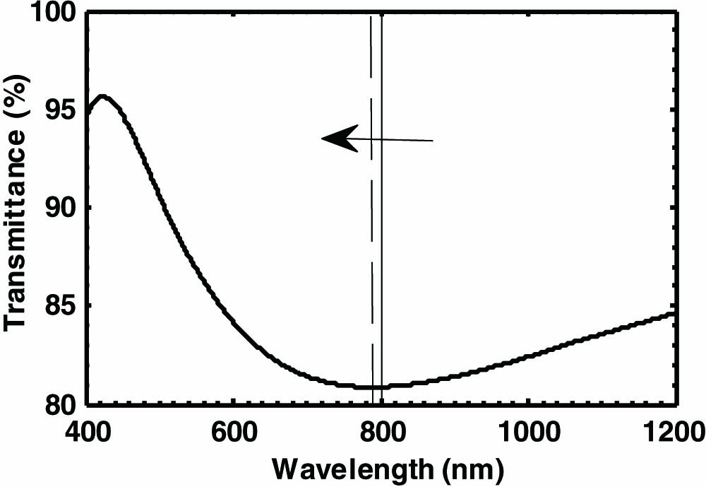
We take a simple single-layer reflection coating as an example to describe the mechanism of the wavelength shift. The coating material and substrate are supposed to be and fused silica. Under the reference wavelength of 800 nm, the quarter-wave thickness coating has a transmission spectrum as shown in Fig. 1. The incident wavelength is set as 800 nm. If the rising temperature is 1000 K, the increase in the refractive index, as calculated by Eq. (8), is 0.026. The selected values of the parameters are listed as follows: the coating thickness is 102.35 nm, , , , and [18,19].
Figure 1.Transmission curve of the single-layer coating and the schematic of the wavelength shift while the temperature heats up.
Therefore, the result of at increases to 0.2533 after the temperature rises, which is approximately equal to the case of in a normal situation, when . This is the so-called “wavelength shift.” There are two points that should be noted here. One is that the precise value of of is unknown, so an approximate value is selected in the calculation. The other is that the refractive index as a function of the wavelength is not linear, so the concept of the spectrum curve shift is not very strict.
The transmission calculation for a multi-layered coating is more complex, because the refractive index and its variation in each layer are different. The precise parameters involved in the calculation are hard to obtain, since the exact characteristic of the transmission curve is hard to establish while the coating temperature is rising. But we can expect that, at a certain wavelength, a higher gradient of the spectrum curve will induce a more dramatic change in the transmission while the temperature is rising, because a higher slope of the transmission curve implies that, at this point, the transmission of the coating is more sensitive to the incident laser. In the case of Fig. 1, the transmission change induced by a laser with a 500 nm wavelength should be larger than that with a wavelength of 800 nm. This is decided by the curve slope of the transmission.
Three customized coating samples were used in the experiment. They had the same coating materials: and a fused silica substrate with a 5 mm thickness. The deposition technique was e-beam evaporation with the same control parameters, such as temperature, pressure, and so on. The reference wavelength was 800 nm, and each layer of the samples had a quarter-wave thickness. The coating system of these three samples is as follows: 1#: , 2#: , and 3#: . Their spectrum curves are shown in Figs. 2, 3, and 4. In the figures, we also present the calculation results, which indicate that the deposition processes had been controlled precisely.
Figure 2.Spectrum curve of 1# with the coating structure.
A ytterbium-doped double-clad fiber laser system was employed in the experiment; it output a continuous single lateral mode laser beam. The wavelength of the laser was 1080 nm. After a working time of about half an hour, the power stability of the laser was tested within . The testing time lasted an hour, during which we read the power meter every 5 min. A lens with a focal length of 400 mm was used to focus the beam. At the position of the samples mounted behind the lens, the beam diameter was about 200 μm (). The transmission testing procedure is to measure the laser power after the coatings until the illuminating time of the laser reaches 5 min and the transmitted power reaches a steady state. Then, we work out the results of the coating transmission. In our experiment, it should be the thermal effects that dominate the laser coating interactions, especially when the maximum power density is moderate, at about on the coating surface. The wavelength of the incident laser and the coating spectrum curves are given in Fig. 5.
Figure 5.Coating spectrum curves and the position of the laser wavelength.
At 1080 nm, the magnitude of the curve slope belonging to 3# is the biggest, followed by 2#. Sample 1# has the lowest curve slope (see Fig. 5). According to the earlier analysis, the sensitivity of the transmission variation of the three samples induced by the laser heating effects should follow the same sequence. Due to the stability of the laser output, we have obtained the extent of the transmission change of the coatings with the increase in the laser power. The results are shown in Fig. 6 in detail. With the increase of the incident laser power, the magnitude of the transmission increases. The value of 3# is the highest, reaching 3.4%, 2# is in the middle, reaching 1.3%, and 1# is so small as to not even be evident. The experimental results are in agreement with the theoretical prediction.
Figure 6.Transmission of the three coatings with the increase of the incident laser power.
For a dielectric coating, the refractive indices of the stack materials determine the transmission curve, and they can be influenced by the laser-induced thermal effects. Thermal expansion leads to a decrease in the mass density, and, as a consequence, lowers the refractive index. The thermo-optical effect is another factor that changes the refractive index during the laser heating process. An approximate relationship between the variation of the refractive index and the thermal effects is deduced by taking these two factors into consideration. When the coating transmission is irradiated by a laser at a certain wavelength, the change in the refractive index is, to some extent, equivalent to the change in the incident wavelength, which is the proposed wavelength shift. When the gradient of the coating transmission curve is higher, the influence of the wavelength shift on the transmission should be more obvious. An experiment testing the coating transmission is carried out to verify this analysis. In the experiment, a 1080 nm continuous fiber laser is used to irradiate three customized coating samples to measure the transmitted power during the increase in the incident power. The result is in accordance with the theoretical prediction.
References
[1] L. Gallais, M. Commandré. Optical Interference Coatings(2013).
[4] D. Schiltz, P. F. Langton, D. Patel, L. Emmert, L. N. Acquaroli, C. Baumgarten, B. Reagan, W. Rudolph, A. Markosyan, R. R. Route, M. Fejer, J. J. Rocca, C. S. Menoni. CLEO: Applications and Technology(2014).