Abstract
An injection-seeded single-resonant optical parametric oscillator (SROPO) with single frequency nanosecond pulsed 2.05 μm wavelength output is presented. Based on two potassium titanyl phosphate crystals and pumped by a 1064 nm single frequency laser pulse, injection seeding is performed successfully by using the ramp-hold-fire technique in a ring cavity with a bow-tie configuration. The SROPO provides 2.65 mJ single frequency signal pulse output with a 17.6 ns pulse duration at a 20 Hz repetition rate. A near-diffraction-limited beam is achieved with a beam quality factor of about 1.2. The spectrum linewidth of the signal pulse is around 26.4 MHz, which is almost the Fourier-transform-limited value.The 2 μm waveband lasers have drawn growing attention for their valuable applications in scientific and technical domains, such as laser medicine, material processing, spectroscopy, metrology, range finding, free-space optical communication, atmospheric remote sensing, and mid-infrared radiation generation[1–9]. Especially in the constantly advancing coherent Doppler wind lidar and integrated path differential absorption lidar (IPDA) for water vapor () or carbon dioxide () concentration profiling, laser diode (LD)-pumped all-solid-state single frequency nanosecond pulsed 2 μm lasers with high beam quality are highly desirable due to their eye safety, compactness, high overall wall plug efficiency, narrow linewidth, good maintainability, excellent reliability, and long lifetime[10,11]. In order to meet such requirements, two kinds of main approaches have been investigated to obtain single frequency 2 μm nanosecond pulsed laser radiation. One of them is injecting a continuous wave (CW) single frequency seeder laser into a -switched laser based on direct emission at 2 μm wavelength from Tm-doped, Ho-doped or Tm, Ho co-doped gain materials. The other one is employing an injection-seeded optical parametric oscillator (OPO) pumped by an all-solid-state 1 μm nanosecond pulsed laser based on nonlinear frequency conversion.
Researchers have gotten many remarkable achievements from an injection-seeded -switched 2 μm laser by use of different pumping methods and cavity length locking techniques[12–15]. In 2006, Yu et al. reported an LD side-pumped injection-seeded Ho:Tm:LuLF -switched laser using the ramp and fire technique, where 100 mJ of pulse energy of a single frequency 2.053 μm laser was achieved with a 185 ns pulse width at a repetition rate of 10 Hz[16]. By utilization of the Pound-Drever-Hall method to stabilize the cavity length, Gibert et al. in 2014 presented a seeder injected single frequency Ho:YLF laser pumped by a Tm fiber laser and realized a single pulse energy of 13 mJ laser output at 2051 nm with a pulse duration of 42 ns at a repetition frequency of 2 kHz[17]. These 2 μm -switched lasers require a complicated cooling system because of their inherent quasi-three-level nature. Besides, the Ho-doped lasers have to strike a balance between good pump absorption and low pump threshold, which limits efficiency and performance[18]. In Tm, Ho co-doped lasers, strong up-conversion loss, and the ground state absorption loss at a high pump level will result in reducing the effective upper level lifetime, increasing the pump threshold, and decreasing the lasing efficiency[17,19–21].
In fact, OPO systems for 2 μm wavelength lasing are capable of avoiding the aforementioned problems and offer several advantages over the -switched direct emission-based 2 μm laser gain mediums. However, till now, there are seldom reports on a 2 μm single frequency nanosecond pulsed laser based on injection-seeded OPO, which might be attributed to the relatively large parametric gain bandwidth around the degenerate wavelength of 2 μm. In 2014, Barria et al. presented a novel doubly resonant entangled-cavity OPO (ECOPO) based on a type II PPLN crystal pumped by a single longitudinal mode 1064 nm Nd:YAG laser[22]. By simultaneously locking the resonator length of the signal cavity and idler cavity, a 2.05 μm single frequency narrow linewidth laser emission with a pulse energy of 32.3 μJ at a repetition rate of 30 Hz was obtained. Due to the low damage threshold of the PPLN crystal, it is not a preferable media for a single frequency nanosecond OPO system for high pulse energy applications.
Sign up for Chinese Optics Letters TOC. Get the latest issue of Chinese Optics Letters delivered right to you!Sign up now
In this Letter, utilizing a stable bow-tie ring cavity in combination with the ramp-hold-fire (RHF) technique, single frequency 2.05 μm wavelength lasing was successfully demonstrated in a single-resonant OPO (SROPO) based on two KTP crystals. To the best of our knowledge, this is the first demonstration of a 2.05 μm single frequency nanosecond pulsed laser output from an injection-seeded KTP OPO. At a repetition rate of 20 Hz, the maximum output pulse energy of 2.65 mJ with a pulse width of around 17.6 ns was obtained. A 26.4 MHz spectrum linewidth of the signal pulse revealed that nearly Fourier-transform-limitation lasing was realized in this KTP SROPO system.
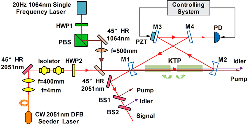
The experimental setup of the injection-seeded 2.05 μm single frequency nanosecond pulsed OPO is schematically shown in Fig. 1. It consists of three parts: a slave OPO, a CW seeder laser, and an electronic controlling system.

Figure 1.Experimental setup of the injection-seeded OPO.
In the experimental arrangement, a four-mirror symmetric bow-tie ring cavity was designed, where the optimized ring cavity consists of two plane-concave mirrors (M1, M2) with a curvature radius of 660 mm and two plane mirrors (M3, M4), and the length of the ring cavity is about 190 mm. The corresponding resonator stability factors is 0.5, while the diameter of the intra-cavity signal beam fundamental transverse mode is about 680 μm.
Two identical KTP crystals are chosen as the nonlinear conversion media to achieve wavelength conversion from 1 to 2 μm. KTP crystals are symmetrically placed with a walk-off-compensation configuration in the middle of two curved mirrors. Each KTP crystal with the size of is cut at , for the type II phase matched condition. The polarization match condition of the OPO process is shown as follows: . Both crystals are wrapped with indium foil and clamped on copper heat sinks for cooling. The entrance and exit end faces of the KTP crystal are anti-reflection (AR) coated at pump, signal, and idler wavelengths.
The coupling curve mirror (M1) is AR coated at the pump wavelength with a transmission of 23% at the signal wavelength. The plane mirror (M3) and curve mirror (M2) are both AR coated for the pump light and high reflection (HR) for the signal light. Another plane mirror (M4) is designed with a transmission of 1% at the signal wavelength so that the interference signal of the seeder laser formed by the repeated round-trip in the cavity could leak out from the resonator with enough intensity to be detected. Even more, mirrors M3, M4, and M2 are all coated with a transmission of 50% at the idler wavelength to realize efficient single-resonant OPO lasing. Mirror M3 is mounted upon a PZT for ring cavity length sweeping.
The OPO is pumped by a 1064 nm single frequency nanosecond pulsed laser at a pulse repetition frequency of 20 Hz[23]. It is capable of providing a maximum single pulse energy of 11.4 mJ with a pulse width of 23.6 ns and a linewidth of 20 MHz. The pump beam is focused into the ring cavity by a plane-convex lens with a focal length of 500 mm, and the pump beam diameter in the center of two KTP crystals is about 683.9 μm, which is well matched with the signal mode in the ring cavity. A combination of a half-wave plate (HWP1) and a polarizing beam splitter (PBS), acting as a variable attenuator, is used to adjust the total pump pulse energy propagating into the ring cavity. A pair of beam splitters (BS1, BS2) are adopted to filter out the residual pump light and idler light.
A distributed feedback (DFB) LD from Nanoplus GmbH is used as the seeder, and its wavelength is centered at 2.05 μm with a nominal linewidth of less than 3 MHz. Two 33 dB Faraday isolators are introduced to prevent feedback from the OPO cavity. The seeder laser is focused by a plane-convex lens with a focal length of 400 mm to realize its spatial mode match with the OPO cavity for maximum seeding efficiency. The focused seeder laser beam diameter is about 685.5 μm in the center of two KTP crystals, which is almost the same as the signal mode size of the ring cavity. A half-wave plate (HWP2) is inserted to adjust the polarization state of the seed laser to meet the polarization requirement of injection. The seeder laser with an output power of about 6 mW is injected into the OPO cavity through the coupler (M1) with a transmission of 23%.
An active electronic feedback controlling system based on the RHF method is designed to make the SROPO cavity resonate with the seeder laser. In each period, the RHF process is started by a trigger signal with a suitable fixed delay before the pump pulse. A ramp voltage is amplified to drive the PZT to sweep the cavity length with at least one free spectral range (FSR) to ensure that a resonance peak is detected for effective injection locking. An InGaAs photodiode (PD) is placed behind mirror M4 to detect the interference signal produced by the seeder beam circulating in the resonator. Once the SROPO cavity length is resonating with the seeder frequency, an interference signal peak can be detected.
The output performance of the injection-seeded SROPO is investigated in detail. Figure 2 shows the OPO output signal pulse energy and pump-to-signal conversion efficiency as a function of input pulse energy in a free running mode and an injection-seeded mode. The measured results reveal that both the OPO output signal pulse energy and pump-to-signal conversion efficiency are growing gradually with the increase of the pump pulse energy. In the free running mode, the measured OPO threshold pump pulse energy is approximately 6.66 mJ, corresponding to a threshold pump intensity of . At a maximum input pump energy of 11.43 mJ, the maximum output signal pulse energy reaches 1.95 mJ with a pump-to-signal conversion efficiency of 17.1%. The slope efficiency of 39.8% is obtained by linearly fitting the experimental data of the output signal pulse energy. However, we find that the injection-seeded OPO threshold pump pulse energy is obviously reduced to 5.62 mJ with a threshold pump intensity of , and the seeded-injection process effectively improves the output energy of the OPO signal pulse and the conversion efficiency at a relatively low pump energy. The maximum OPO output signal pulse energy with seeder-injection is 1.35 times of that from the free running mode, corresponding to 2.65 mJ pulse energy output with a conversion efficiency of 23.2% from pump to signal; the slope efficiency is around 40.3%.
Figure 2.(Color online) OPO output signal pulse energy and pump-to-signal conversion efficiency as a function of pump pulse energy in the free running mode and injection-seeded mode.
The beam quality factor of the signal beam is measured by an infrared camera (Pyrocam IV). The signal beam diameter is recorded at different positions along its propagation direction after being focused by a plane-convex lens with a focal length of 400 mm, fitting these measured data with the Gaussian beam propagation equation indicates that the signal beam quality factors are calculated to be 1.2 and 1.1 in the horizontal and vertical directions, respectively. Figure 3 depicts the measured result of signal beam quality on the condition of 2.65 mJ signal pulse output, and a nearly diffraction-limited signal beam has been achieved from this SROPO ring cavity.
Figure 3.(Color online) Signal beam quality of the injection-seeded OPO.
On the same condition of 11.43 mJ pump pulse input, the OPO input pump pulse and output signal pulse in combination with the depleted pump pulse are compared between the free running mode and seed injection mode, as displayed in Fig. 4. A phenomenon of frequency beating induced by multilongitudinal mode oscillation can be observed in a free running OPO signal pulse trace, but the profile of the signal pulse from the seeder-injection mode is quite smooth due to only one longitudinal mode lasing. The OPO output signal pulse width is around 17.8 ns with a pulse rise time of 5.9 ns without seeder-injection. After seeded-injection, the OPO output signal pulse build time will be reduced. As a result, the measured injection-seeded OPO signal pulse rise time drops to 3.6 ns with a pulse duration of 17.6 ns. The depleted pump pulse with seeded-injection presents a deeper sunken signal pump pulse on the falling edge than that of a free running OPO. Moreover, these pulse profiles also show that there is no back conversion induced at the highest pump level, as it is neither sunken in the center of the signal pulse nor bulged in the falling edge of the depleted pump pulse.
Figure 4.(Color online) Laser pulse temporal profile. (a) OPO output signal pulse in free running and injection-seeded mode; (b) OPO depleted pump pulse in free running and injection-seeded mode; (c) input pump pulse profile.
The spectrum of the signal pulse in free running mode and injection-seeded mode are measured by an optical spectrum analyzer (YokoGaWa AQ6375) with a resolution of 0.05 nm at 2.05 μm. As described in Fig. 5, the free running OPO output signal beam spectrum is centered at 2051.65 nm with a spectral width (FWHM) of 1.16 nm. Meanwhile, the injection-seeded OPO output signal spectrum is also centered at 2051.65 nm with a spectral linewidth of less than 0.05 nm.
Figure 5.(Color online) OPO output signal spectrum in free running mode and injection-seeded mode.
In order to determinate the spectral linewidth of the signal laser pulse output from the injection-seeding OPO, a home-built linewidth measurement setup based on the optical heterodyne technique is employed, as shown in Fig. 6. Another polarization-maintaining (PM) fiber-coupled 2051 nm DFB single frequency CW laser is used as an offset local oscillator for the heterodyne mixing. The CW laser is tuned by a temperature controller to have a frequency difference of about 360 MHz with the signal pulse of an OPO. An attenuator is inserted following the signal laser to make sure that two laser beams have an identical peak power. A plane-convex lens with a focal length of 400 mm is introduced to coupling the pulsed laser into a 3 dB PM fiber combiner. The CW laser and the pulsed laser form an optical beat in the combiner. The beat signal is detected by an InGaAs PD with a 12.5 GHz bandwidth and then sampled by a data acquisition system (DAQ) with sample rate of 2 GS/s (NI-PCI 5154). A half-wave plate (HWP3) is inserted to adjust the polarization state of the pulse laser for maximizing the beat signal. The linewidth of the pulsed signal laser at 2.05 μm is derived by implementing a fast Fourier transform (FFT) algorithm on the heterodyne beat signal. A typical heterodyne beat signal and its spectrum are shown in Fig. 7. The FWHM of the pulse signal spectrum is approximately 26.4 MHz. Considering the pulse width of 17.6 ns, nearly Fourier-transform-limited single frequency pulsed signal laser output is obtained.
Figure 6.Schematic of measurement setup based on the optical heterodyne technique.
Figure 7.Measurement of spectral linewidth. (a) Beat signal; (b) the spectrum of the beat signal.
In conclusion, a seeder-injected single frequency nanosecond pulsed 2.05 μm OPO pumped by a 1.064 μm single frequency pulsed laser is developed, and stable single longitudinal mode lasing is successfully demonstrated. In the stable bow-tie ring cavity, two type II phase matching KTP crystals are placed in the walk-off-compensated mode. When the pump single pulse energy reaches 11.43 mJ at a repetition rate of 20 Hz, a 2.05 μm single frequency signal laser output with a pulse energy of 2.65 mJ is obtained, whose pulse width is around 17.6 ns. The maximum pump-to-signal conversion efficiency is about 23.2%. The linewidth of the signal laser is around 26.4 MHz, and the beam quality factor of the 2.05 μm laser is 1.2 and 1.1 for and directions, respectively. To the best of our knowledge, this is the first time of 2.05 μm single frequency nanosecond pulse lasing in a seeder injected KTP OPO. It is believed that this SROPO system is a good candidate for coherent Doppler lidar and DIAL applications for or concentration profiling.
References
[1] X. Zhang, Y. Ju, Y. Wang. Chin. Opt. Lett., 3, 463(2005).
[2] W. Tao, C. Sun, B. Xue, D. Yang, M. Wang, C. Cai, Y. Shan. Lasers Med. Sci., 32, 351(2017).
[3] A. Dergachev, D. Armstrong, A. Smith, T. Drake, M. Dubois. Opt. Express, 15, 14404(2007).
[4] O. L. Antipov, N. G. Zakharov, M. Fedorov, N. M. Shakhova, N. N. Prodanets, L. B. Snopova, V. V. Sharkov, R. Sroka. Med. Laser Appl., 26, 67(2011).
[5] F. Gibert, P. H. Flamant, J. Cuesta, D. Bruneau. J. Atmos. Oceanic Technol., 25, 1477(2008).
[6] U. N. Singh, T. Shuman, F. E. Hovis, U. N. Singh, M. Petros, J. Yu, M. J. Kavaya. Proc. SPIE, 8872, 887205(2013).
[7] S. Shu, T. Yu, R. Liu, J. Hou, X. Hou, W. Chen. Chin. Opt. Lett., 9, 091407(2011).
[8] W. Liu, Y. Ju, T. Dai, L. Xu, J. Yuan, C. Yang, B. Yao, X. Duan. Chin. Opt. Lett., 14, 091401(2016).
[9] E. Ji, Q. Liu, Z. Hu, P. Yan, M. Gong. Chin. Opt. Lett., 13, 121402(2015).
[10] U. N. Singh, D. N. Nicolae, D. Mammez, E. Cadiou, J.-B. Dherbecourt, M. Raybaut, J.-M. Melkonian, A. Godard, G. Gorju, J. Pelon, M. Lefebvre. Proc. SPIE, 9645, 964507(2015).
[11] U. N. Singh, B. M. Walsh, J. Yu, M. Petros, M. J. Kavaya, T. F. Refaat, N. P. Barnes. Opt. Mater. Express, 5, 827(2015).
[12] T.-Y. Dai, Y.-L. Ju, X.-M. Duan, Y.-J. Shen, B.-Q. Yao, Y.-Z. Wang. Appl. Phys. Express, 5, 082702(2012).
[13] J. Yu, U. N. Singh, N. P. Barnes, M. Petros. Opt. Lett., 23, 780(1998).
[14] Y. Bai, J. Yu, M. Petros, P. Petzar, B. Trieu, H. Lee, U. Singh. Advanced Solid-State Photonics, WB22(2009).
[15] Q. X. Na, C. Q. Gao, Q. Wang, Y. X. Zhang, M. W. Gao, Q. Ye, Y. Li. Laser Phys. Lett., 13, 095003(2016).
[16] U. N. Singh, M. Petros, T. Itabe, J. Yu, B. Trieu, D. N. Rao, Y. Bai, P. Petzar, U. N. Singh. Proc. SPIE, 6409, 64091A(2006).
[17] F. Gibert, D. Edouart, C. Cénac, F. Le Mounier. Appl. Phys. B, 116, 967(2014).
[18] W. A. Clarkson, R. K. Shori, W. Koen, C. Jacobs, L. Wu, H. J. Strauss. Proc. SPIE, 9342, 93421Y(2015).
[19] T. Y. Dai, Y. L. Ju, X. M. Duan, W. Liu, B. Q. Yao, Y. Z. Wang. Appl. Phys. B, 111, 89(2013).
[20] G. Rustad, K. Stenersen. IEEE J. Quantum Electron., 32, 1645(1996).
[21] T. Y. Fan, G. Huber, R. L. Byer, P. Mitzscherlich. IEEE J. Quantum Electron., 24, 924(1988).
[22] J. Barrientos Barria, D. Mammez, E. Cadiou, J. B. Dherbecourt, M. Raybaut, T. Schmid, A. Bresson, J. M. Melkonian, A. Godard, J. Pelon, M. Lefebvre. Opt. Lett., 39, 6719(2014).
[23] D. Wei, X. Ma, R. Zhu, C. Zhou, J. Liu, X. Zhu, W. Chen. Laser Phys. Lett., 12, 095004(2015).