A high power linearly polarized tunable Raman random fiber laser (RFL) was studied theoretically and experimentally. The parameters required for the system design were obtained through numerical simulation, based on which a hundred-watt-level linearly polarized tunable RFL was successfully demonstrated. The central wavelength can be continuously tuned from 1113.76 to 1137.44 nm, and the output power exceeds 100 W for all of the lasing wavelengths with the polarization extinction ratio (PER) exceeding 20 dB at the maximum output power. Besides, the linewidth, spectral evolution, and temporal dynamics of a specified wavelength (1124.72 nm) were investigated in detail. Moreover, the theoretical results and the experimental results fit well. To the best of our knowledge, this is the first time for a hundred-watt-level linearly polarized tunable RFL ever reported.
As a kind of laser that utilizes Raman gain and random distributed feedback of Rayleigh scattering in ultra-long optical fibers instead of well-defined cavity mirrors, the Raman random fiber laser (RFL)[1] has attracted much attention in recent years owing to its unique features, like mode-free property, simple structure, and low coherence length[2], which could enable potential applications in fiber sensing, optical pumping, nonlinear frequency conversion, and so on[3–7]. Up to now, exploration on RFLs has already covered tremendous areas, including power scaling[8–10], operation waveband extending[11], wavelength tunability[12–16], narrow-linewidth operation[17–19], linearly polarized operation[20–22], pulsed operation[23,24], and so forth, among which wavelength tunability is an important field that can extend the application scenarios of RFLs.
Compared with conventional wavelength tunable fiber lasers based on rare-earth gain, whose tunable range is partly limited by the emission spectra of the rare-earth dopants, wavelength tunable RFLs can be achieved by changing the wavelength of the pump source combined with the Raman gain[2,5]. Several tunable RFLs based on different schematics have been demonstrated. In 2011, Babin et al. reported a tunable RFL that can be continuously tuned from 1535 to 1570 nm with maximum output power of [12]. In 2013, Zhu et al. demonstrated a tunable multiwavelength RFL working from 1553.9 to 1565.4 nm utilizing a Fabry–Perot cavity combined with a long-period fiber-gratings-based Mach–Zehnder interferometer[13]. In 2014, Wang et al. proposed a tunable RFL with the help of a tunable fiber Fabry–Perot interferometer, the wavelength of which can be tuned from 1525 to 1565 nm[14]. In 2015, Du et al. demonstrated a tunable fiber laser, where a 1-km-long single-mode fiber is used to provide random distributed feedback, and the wavelength is tunable from 1040 to 1090 nm with watt-level output power[15]. Most recently, Zhang et al. proposed an RFL with ultra-broad tunable range from 1 to 1.9 μm by continuously adjusting the pump laser wavelength and increasing the pump power[16].
It is to be noted that all the abovementioned wavelength tunable RFLs are randomly polarized, and the output is relatively low (mostly no more than the ten-watt level). In practice, a linearly polarized laser with high power is desired in some application areas. For example, a powerful visible or mid-infrared laser with a higher efficiency based on nonlinear frequency conversion[7,25] could be achieved if a linearly polarized high power RFL is employed. Therefore, a linearly polarized tunable RFL with high output power is of significant importance for practical use.
Sign up for Chinese Optics Letters TOC. Get the latest issue of Chinese Optics Letters delivered right to you!Sign up now
In this Letter, we will study and prove the feasibility of a high power hundred-watt-level linearly polarized tunable RFL for the first time, to the best of our knowledge. Through numerical analysis, the parameters required for system design are obtained. Then, we build a high power linearly polarized tunable RFL according to the instructions of the theoretical calculations. Based on a homemade tunable Yb-doped fiber laser as the pump, an over 100 W high power linearly polarized RFL is successfully achieved with a tuning range of 23.68 nm. The polarization extinction ratio (PER) under hundred-watt-level operation for all wavelengths is measured to be more than 20 dB.
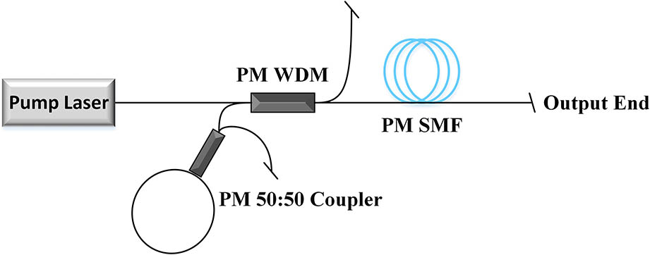
First of all, the theoretical study is carried out to obtain the parameters, including the length of the passive fiber and pump power, needed for designing a hundred-watt-level RFL. The experimental setup of the RFL that we intend to use is based on a half-open cavity structure, as shown in Fig. 1. The pump power is provided by a tunable fiber laser with linearly polarized output, which is injected into a piece of polarization maintaining (PM) single-mode passive fiber (SMF) through a PM wavelength division multiplexer (WDM). A coupler is used as a Sagnac fiber loop mirror to provide broadband reflection, which is connected with the rest port of the PM WDM.
Taking account of this experimental configuration, the corresponding theoretical model is set up based on the classical steady-state light propagation equations[9,20,26,27]: where the subscripts 0, 1, 2 stand for the pump light, the first-order Stokes light, and the second-order Stokes light, respectively. The superscripts + and - represent the forward and backward propagating waves, correspondingly. The parameter P stands for the power at different positions. and are the wavelength and corresponding wave frequency. , , and are the Raman gain coefficient, signal loss, and Rayleigh backscattering coefficient, respectively. is the Planck constant, and is the Boltzmann constant; is the bandwidth of Stokes light. The parameter represents the population of the photon that introduces the noise from spontaneous Raman scattering. The values of all of the parameters used in the numerical calculation are listed in Table 1.
Boundary conditions are as follows: where is the input pump power, and and stand for the reflectivity at the left and right end, respectively.
In the simulation, the core and cladding diameters of the passive fiber are 10 and 125 μm, respectively.
In order to determine the length of the passive fiber needed in a hundred-watt-level RFL, the maximum output power of the first-order Stokes light for passive fibers with different lengths is simulated. Based on the theoretical model, the maximum output power of the first-order Stokes light varying with different passive fiber lengths is depicted in Fig. 2(a). As indicated in this figure, the maximum output power of the first-order Stokes light decreases as the length of the passive fiber increases. When the length of the passive fiber is less than 150 m, the output powers of the first-order Stokes light could possibly be beyond 100 W. Considering that we will develop a tunable RFL with the help of a wavelength tunable pump source, the Raman gain difference at different wavelengths should be considered. Based on this concern, a relatively short passive fiber of 130 m is chosen in the RFL.
Figure 2.(a) The maximum power of the first-order Stokes light versus the length of the passive fiber. (b) The simulated results of the residual pump, first- and second-order Stokes light.
On this condition, in order to determine the minimum pump power needed for a hundred-watt-level RFL, we set the maximum output power of the pump source to 200 W in the theoretical simulation. Other parameters in this simulation remain unchanged. The output power variation of the residual pump, the first-order Stokes light, and the second-order Stokes light as a function of pump power is depicted in Fig. 2(b). The threshold of the first-order Stokes light is . The output power of the first-order Stokes light reaches 100 W at the pump power of 140 W and reaches its maximum of 125 W at the pump power of 165 W. Therefore, about 140 W of pump power is needed in order to ensure hundred-watt output.
Based on these obtained structural parameters, we set up a linearly polarized tunable RFL, as shown in Fig. 3(a). The pump source is a tunable Yb-doped fiber amplifier consisting of a tunable seed laser together with two-stage amplifiers, as shown in Fig. 3(b). The ring cavity laser is pumped by a 976 nm single-mode laser diode through a . An optical tunable filter is adopted to vary the output wavelength, and a piece of 2-m-long single-mode Yb-doped fiber is used to provide active gain. The 20% port of a output coupler is used to deliver laser output, which is spliced with a polarization beam splitter (PBS) to polarize the propagating waves. Then, the output of the PBS is delivered into the PM pre-amplifier and the PM main amplifier. In the experiment, the power of the tunable seed laser exceeds 50 mW from 1057.5 to 1080 nm. The power is boosted to be by the pre-amplifier, and then further scaled to (wavelength-dependent) by the main amplifier.
Figure 3.(a) Experimental setup of a tunable RFL. (b) Detailed setup of the tunable pump source (AMP1, pre-amplifier; AMP2, main amplifier; PBS, polarization beam splitter; OTF, optical tunable filter; GDF, germanium-doped fiber; ISO, isolator). (c) Experimental setup for PER measurement.
As shown in Fig. 3(a), the output power from the main amplifier is injected into the PM SMF, which is a piece of 130.7-m-long germanium-doped fiber (, ) via the 1070 port of a high power WDM. This piece of SMF is utilized to provide Raman gain and random distributed feedback. The loss coefficient and Rayleigh backscattering coefficient of this SMF are about and around 1070 nm, respectively. The Raman gain coefficient is . A fiber loop mirror made of a PM coupler with a central wavelength of 1120 nm is spliced to the WDM to form a half-cavity with broadband reflection. The output end of the PM GDF is cleaved with an 8° angle. The PER of the RFL could be measured by using a collimator, a dichroic beam splitter, a half-wave plate (working at 1120 nm), a PBS, and two power meters, as shown in Fig. 3(c). At the output end, we use a collimator to collimate the output light. A dichroic beam splitter is used to extract the first-order Stokes light from the output light. With the help of the half-wave plate and PBS, the powers in the two orthogonal directions could be measured, and the PER of the output radiation could be calculated as , where and are the values of major and minor axes of the polarization ellipse.
The properties of the homemade pump source, including the output power and linewidth of each pump wavelength, are measured and depicted in Fig. 4(a). The output powers reach 153.0, 141.9, 164.0, 151.1, 139.4, and 139.4 W at the wavelengths of 1057.5, 1062.5, 1067.5, 1072.5, 1077.5, and 1080.0 nm, respectively. The output spectra at the maximal output power of each wavelength are normalized and plotted in a linear coordinate, as shown in Fig. 4(b), and the corresponding linewidths are 0.39, 0.57, 0.56, 0.54, 0.21, and 0.48 nm, respectively.
Figure 4.(a) Maximum output power and corresponding linewidth of the pump source. (b) The spectra of the pump source.
In the experiment, the lasing threshold of Raman random lasing is tested to be around 75 W. As the wavelength of the pump source is continuously tuned from 1057.5 to 1080 nm, the central wavelength of the RFL varies from 1113.76 to 1137.44 nm accordingly. The output spectra of the first- and second-order Stokes light stimulated by different pump wavelengths are shown in a linear coordinate, as depicted in Fig. 5(a). The total output powers of each wavelength range from 120 to 136.5 W with the power of the first-order Stokes all exceeding 100 W, reaching 105.18, 100.59, 126.77, 120.99, 100.33, and 113 W at 1113.76, 1119.96, 1124.72, 1129.96, 1135.56, and 1137.44 nm, respectively, as shown in Fig. 5(b). The linewidths of these abovementioned six wavelengths at the maximum output power are also measured, being 5.35, 4.47, 4.48, 6.93, 6.5, and 3.61 nm, respectively.
Figure 5.(a) Spectra of the RFL. (b) Power and corresponding linewidth of the first-order Stokes light at different wavelengths.
In order to study the output power and spectral evolution characteristics of this RFL, the output wavelength of 1124.72 nm, at which the laser delivers the maximal first-order Stokes output power, is selected. Figure 6(a) shows the output power as a function of the pump power. When the pump power is below the lasing threshold (), only the transmitted pump light can be observed. As the pump power grows higher than 79.4 W, the residual pump light becomes weaker as it converts to RFL. In the meantime, the power of the RFL grows rapidly to 126.77 W at the maximum pump power of 164.0 W. The corresponding optical-to-optical conversion efficiency of pump light to RFL is 77.3%. The second-order Stokes light starts to appear at the pump power of 137.4 W and gradually grows to 6.34 W at the maximum pump power. Figure 6(b) shows the spectra at different pump powers. As the output power increases, the spectra variation of the pump wavelength (1067.5 nm), first-order Stokes light (1124.72 nm), and second-order Stokes light (1178.96 nm) can be clearly distinguished, which fits that of Fig. 6(a) as well. Figs. 6(c) and 6(d) denote the spectrum evolution of the first-order Stokes light. When the pump power is low, the output spectrum tends to have dual peaks corresponding to the typical well-known dual peaks in the Raman gain spectrum. As the pump power increases, the dual peaks start to merge, which could be explained by the theory proposed in Ref. [28]. As a result, the linewidth shows an overall tendency of increasing, as shown in Figs. 6(c) and 6(d), which can be attributed to spectral broadening caused by self-phase modulation (SPM) and cross-phase modulation (XPM).
Figure 6.(a) Output power evolution of the random laser and (b) the output spectra of the RFL. (c) The spectra and (d) the linewidth evolution of the first-order Stokes light.
The polarization characteristics of the pump source as well as the first-order Stokes light at different wavelengths are also investigated. Fig. 7(a) gives the PER of different wavelengths and their corresponding first-order Stokes lights at each of their own maximum powers, respectively. The PERs of the pump source are all around 20 dB at different wavelengths, while the PERs of the corresponding first-order Stokes light are all higher than that of the pump source. This phenomenon could possibly be attributed to the Raman purification effect. To understand the PER evolution characteristics more specifically, the PER of the 1067.5 nm pump light and RFL generated at this pump wavelength is chosen to be studied, as shown in Fig. 7(b). When the output power is less than 79.4 W, the output power is mainly transmitted pump power, the PER of which is around 20 dB. When the output power is higher than 79.4 W, the intensity of the first Stokes light becomes higher gradually, and the PER decreases from 23.4 dB to a stable value of around 20.7 dB.
Figure 7.(a) PER of the pump source and the corresponding first-order Stokes light at the maximum output power. (b) The PER evolution of the pump power and corresponding first-order Stokes light at the pump wavelength of 1067.5 nm.
We have recorded the radio frequency and temporal behavior of the random laser output at the wavelength of 1124.72 nm. As shown in Fig. 8, there is no longitudinal mode beating corresponding to spacing, where , , and is the light speed in the vacuum. The inset of Fig. 8 is the temporal dynamics of the laser output in a time scale of milliseconds, which is recorded by a photon detector with a bandwidth of 1.2 GHz and an oscilloscope with a bandwidth 1 GHz. The standard deviation of the temporal trace is , indicating that this laser possesses good temporal stability. The temporal behavior combined with the radio frequency spectrum can prove that the laser works in the random lasing regime.
Figure 8.Radio frequency of the random laser at 1124.72 nm. Inset: the temporal trace of the laser output.
We have also simulated the output characteristics of the RFL when the pump wavelength is 1067.5 nm based on the aforementioned theoretical model and compared with experimental ones. The corresponding output wavelengths of the first- and second-order Stokes light are set to be 1124.72 and 1178.96 nm, which are the same as the experimental results. The output powers of the residual pump, first-order Stokes light, and second-order Stokes light obtained from theoretical analysis and experimental results are depicted in Fig. 9. The overall tendency of the experimental results and the simulation fits well. The deviation is acceptable since parameters, like the parasitic reflection of the output end and the intrinsic loss difference of optical components at different wavelengths, might vary with those parameters used in the simulation.
Figure 9.Comparison between simulation results and experimental results.
In conclusion, the theoretical model of an RFL based on light propagation equations is studied, and parameters for designing a hundred-watt-level RFL are obtained through numerical simulation. According to the simulation results, we demonstrate a linearly polarized tunable RFL with hundred-watt output power. The theoretical model fits well with the experimental results. The wavelength of the RFL can be continuously tuned within a 23.68 nm wavelength range. The output power exceeds 100 W for all the lasing wavelengths and the PER exceeds 20 dB at the maximum output power. The PERs of the pump source and the RFL are investigated, which reveals that the PER of the RFL decreases to steady values as the pump power increases, but it is still higher than the PER of the pump light. To the best of our knowledge, this is the first demonstration of a linearly polarized tunable RFL with hundred-watt output power. This tunable RFL could provide a useful light source for a wide range of applications. Moreover, an RFL with higher output power and wider tunable range can hopefully be achieved if high power components and broadband WDM are adopted.