A highly linear W-band receiver front-end based on higher-order optical sideband (OSB) processing is proposed and experimentally demonstrated. Two-tone analysis shows that by manipulating higher-order OSBs, the third-order intermodulation distortion (IMD3) introduced by optoelectronic components (mainly modulators) in the receiver front-end can be further suppressed, and a 9 dB improvement of the ratio of the fundamental and IMD3 can be attained. In the experiment, the spurious-free dynamic range of the W-band receiver front-end is up to , with improvement by 9 dB compared with that of only processing the five OSBs.
Combining with the advantages of fiber optics, such as large bandwidth, low loss, and immunity to electromagnetic interference, radio-over-fiber (ROF) techniques provide a more promising future for millimeter-wave (MMW) application systems, such as broadband wireless access networks, radar systems, and electronic warfare systems[1–4]. In MMW ROF links, the W-band (75–110 GHz) has attracted increasing interest due to relatively low atmospheric loss and large unregulated bandwidth[5,6]. For a W-band receiver front-end based on photonic technologies, a radio frequency (RF) signal is first down-converted to intermediate frequency (IF) by a W-band balanced mixer and then modulated onto a lightwave at a Mach–Zehnder modulator (MZM)[7,8]. These electrical and optical devices (mainly modulators) can lead to nonlinear distortion, which degrades the dynamic range of systems[9].
An important figure of merit that can reflect the impact of nonlinear distortion on these application systems is the spurious-free dynamic range (SFDR). The third-order intermodulation distortion (IMD3) as the main nonlinear distortion factor limits the SFDR, since it is closest to fundamental signals and cannot be filtered out[9]. In past decades, many compensation techniques have been presented to suppress the IMD3 and enhance the SFDR, which include electrical and optical compensation[10–23]. Although digital linearization techniques like pre-distortion, and digital post-processing dependent on digital signal processing (DSP) can achieve a recorded SFDR, the limited bandwidth of electric circuits will restrict high-frequency application[10–12]. In an optical domain, many approaches are achieved by specially designed modulators, such as a single-drive dual-parallel MZM (DPMZM)[13], a dual-drive DPMZM[14,15], a mixed polarization dual-electrode MZM (DEMZM)[16], a polarization modulator (PolM)[17], or two DPMZMs in parallel[18]. By using these modulators, two or more sources of the IMD3 are generated to directly cancel each other. However, these modulators are difficult to use for controlling the bias point drift and increasing the complexity of systems. Recently, a compensation method based on optical spectrum processing (OSP) is proposed, which is independent of the special modulators and appropriate for conventional ROF links[19–23]. In our recent work[19–23], by manipulating five optical sidebands (OSBs), the output IMD3 of the radio signal can be greatly suppressed. However, the SFDR in the W-band ROF links still cannot meet the requirements of the practical application systems. Also, how to improve SFDR is still a problem.
In this Letter, an electro-optic hybrid W-band receiver front-end with a higher SFDR is proposed and experimentally demonstrated. By utilizing higher-order OSBs, together with shifting the phase of the second-order OSBs (2-OSBs), and attenuating the amplitude of the optical carrier sideband (OCB) [i.e., zeroth-order OSB (0-OSB)], the SFDR performance improvement in the W-band receiver front-end is obtained.
Sign up for Chinese Optics Letters TOC. Get the latest issue of Chinese Optics Letters delivered right to you!Sign up now
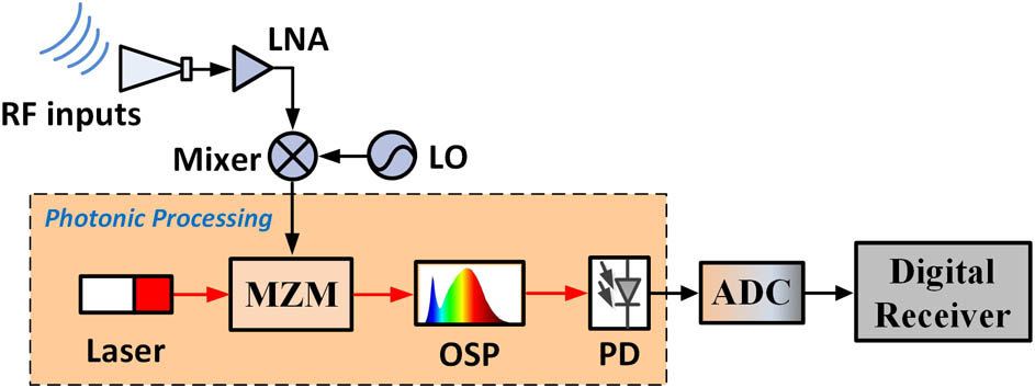
The block diagram of an electro-optic hybrid W-band receiver front-end is shown in Fig. 1. An RF signal at the W-band is first down-converted to an IF because of the performance and price constraints of high-frequency modulators[24]. Next, the IF signal is modulated onto a light signal, and then is processed with an optical signal processor to suppress the IMD3.
Figure 1.Block diagram of an electro-optic hybrid W-band receiver front-end. LNA, low noise amplifier.
To probe the evolution of the IMD3 in the electrical–optical (E/O) and optical–electrical (O/E) conversion, a spectrum analysis based on a two-tone signal is undertaken. In the theoretical analysis, the nonlinear distortion generated by electrical mixing is not considered, since it has no effect on the OSB’s processing. So, we assumed that the IF two-tone signal is where and are the angular frequencies of the IF two-tone signal, and is its amplitude value. The IF two-tone signal is then fed into a MZM, which is operated at the quadrature point to achieve double sideband (DSB) modulation.
The electrical field at the output of the MZM can be written as where and are the intensity and angle frequency of the input optical carrier, , , and represent the half-wave voltage, the direct-current (DC) bias voltage, and the shifted phase of the MZM, respectively. For simplicity, we neglect the insert loss of the MZM. By replacing with Eq. (1) and using the Bessel expansion, Eq. (2) can be further expressed as where is the modulation depth of the output signal, is the constant shifted phase, represents the order of the OSBs, and is the Bessel function of the first kind of order . The terms of order, in Eq. (3), are chosen to probe the effect of higher-order OSBs on nonlinearity compensation. As for , their contributions are negligible. Thus, there are seven OSBs at the output of the MZM: 0-OSB, -OSB, -OSB, and -OSB, as shown in Fig. 2(a).
Figure 2.Spectrum evolution. (a) The optical spectrum at the output of the MZM. (b) The electrical frequency components after the PD, without OSP and with OSP.
If these OSBs beat with each other by a photodetector (PD), the electrical spectrum bands (ESBs) from the zeroth-order to the sixth-order will be generated. However, they can be filtered out by an electrical bandpass filter (BPF) except for the first-order ESB (1-ESB), including the needed fundamental tones[9,20]. For the fundamental tones and the IMD3s in the 1-ESB that are mainly analyzed, they can be generated by beating with the adjacent OSBs, which is illustrated in Fig. 2(b). Hence, there are six sources for all frequencies in the 1-ESB, which are divided into three groups: , , and , as shown in Fig. 2(b). Without OSB processing, the phase of the fundamental tones in and are totally the same, and different than that in , while the phase of the IMD3s in are the same as that in . For the amplitude of these sources, is larger than and . Thus, we can adjust the amplitude of the 0-OSB and the shifted phase of the -OSB to cancel out the six sources of the IMD3. For theoretical analysis, we assume that the shifted phase of the -OSB is , the attenuation for the 0-OSB is , and we extract the terms of the order in Eq. (3) so that Eq. (3) can be rewritten as where , , , , correspond to n-OSBs. By using the formula , where is the responsivity of the PD, the fundamental tone and the IMD3 of the 1-ESB can be given by where and , , 1, 2, and , 2, 3 are the coefficients that can be obtained by Eq. (4). Compared with Ref. [19], the third terms in Eqs. (5) and (6) are taken into account in this Letter, which, as we can see from Fig. 3, brings about SFDR improvement.
Figure 3.Simulation results of the RFI versus the attenuation of the 0-OSB .
Figure 3 shows the simulation results of the change of the ratio of the fundamental and IMD3 (RFI) with the 0-OSB attenuation , where the dashed lines and solid lines indicate five and seven OSBs to be considered, respectively. It can be seen that -OSBs have an impact on the IMD3 suppression. When shifted phase , attenuation and m are , and 0.4, respectively, the RFI can reach 75.5 dB, which is improved about 9 dB compared to that with only -OSBs considered.
Figure 4 shows the schematic diagram of the experimental setup. The electro-optic hybrid W-band receiver front-end is designed to demonstrate the aforementioned nonlinear compensation strategy. A W-band two-tone signal with frequencies of 93.98 and 94.02 GHz is generated with a vector network analyzer (VNA, ZVA67) together with two converters (ZVA-Z110). This two-tone signal is down-converted to an IF through mixing with the sextupled microwave source (MS, 12.5 GHz). After mixing, the IF two-tone signal with a center frequency of 19 GHz and an interval of 40 MHz is amplified by a power amplifier (PA), and then through a BPF applied to a 40 GHz intensity modulator (MX-LN-40, MZM), which is biased at the quadrature point. Here, a waveshaper is used as an OSP, which is based on solid-state liquid crystal on silicon (LCoS), and can independently manipulate the phase and amplitude of the input optical spectrum[25]. By programmatically controlling the waveshaper, the desired phase and attenuation of the OSBs can be realized. An erbium-doped fiber amplifier (EDFA) is used to amplify the optical signal after being processed, which can maintain the input power of the PD (u2t, XPDV3120R) at about 7 dBm. After the square law detection, the electrical signal is analyzed by an electrical signal analyzer (ESA, Agilent N9030A).
Figure 4.Schematic diagram of the experimental setup. PC, polarization controller.
Figure 5 shows the measured SFDR of the W-band receiver front-end. The squares and triangles indicate the measured power of the fundamental tone and the IMD3 in real time at the ESA, respectively, and the curves are obtained by the linear fitting of the measured data. The average noise level measured with the ESA is . From Fig. 5, it can be seen that without any compensation method, the SFDR of the W-band receiver front-end is around , and with the method in Ref. [19], the SFDR value is increased to . By processing the higher-order OSBs, the SFDR is further enhanced to with a 9 dB improvement compared to that of the five OSBs processing, and a 20 dB improvement compared to that without compensation. In addition, it can be seen that the fundamental signals with five OSBs and seven OSBs processing have a power less than that without IMD3 compensation by 11 and 6 dB, respectively. The fundamental signal with seven OSBs processing has a power of more than that with five OSBs by 5 dB. The phenomenon can be illustrated by the third term in Eq. (5), which can give a power contribution to the fundamental tone with seven OSBs considered.
Figure 5.Measured SFDR considered with seven OSBs (solid line), five OSBs (dashed line), and without compensation (dotted line).
In conclusion, a W-band receiver front-end with a higher SFDR is proposed and experimentally demonstrated. In this receiver front-end, the SFDR improvement is obtained by higher-order OSB processing, which does not required digital pre-distortion or specific modulators. The IMD3 introduced by optoelectronic components can be well suppressed by manipulating both the amplitude and phase of OSBS by up to -OSBs. The experimental results show that the SFDR of the proposed system is increased from 112.8 to .
[21] J. Li, Y. C. Zhang, S. Yu, W. Gu. IEEE Photon. J., 6, 1(2014).
[22] J. Chen, D. Zhu, S. Pan. 2016 25th Wireless and Optical Communication Conference (WOCC)(2016).
[23] Z. Li, S. Li, X. Zheng, J. Luo, H. Zhang, B. Zhou. Optoelectronics and Communications Conference (OECC) Held Jointly with 2016 International Conference on Photonics in Switching (PS)(2016).