Holographic head-mounted display (HHMD) is a specific application of holography. The previous conventional computer-generated hologram (CGH) generation method has a large redundancy and suffers from a heavy computing burden in the HHMD. A low redundancy and fast calculation method is presented for a CGH that is suitable for an HHMD with the effective diffraction area recording method. For the limited pupil size of an observing eye, the size of the area producing an effective wavefront is very small, and the calculated amount can be dramatically reduced. A numerical simulation and an augmented virtual reality experimental system are presented to verify the proposed method. 1.5% of the calculation consumption of the conventional CGH generation method is used, and good holographically reconstructed images can be observed.
As one of the next-generation mobile devices to present information in a different manner, instead of the current hand-portable display screen, the head-mounted display (HMD) is making continuous and rapid progress. The most common principle in an HMD is similar to a magnifier that projects images on a microdisplay into the natural focus range of the human eye[1,2]. However, such an approach confronts the mismatch of convergence and accommodation. Light field display[3,4] can solve the confliction, unfortunately at the cost of spatial resolution reduction. Holography is known as the ultimate three-dimensional (3D) display solution that can reconstruct the wavefront of a 3D object[5]. It can offer all the depth cues, including correct convergence, accommodation, binocular disparity, and retinal defocus. Therefore, holographic display shows its high potential both in naked-eye display and in HMD. The first holographic head-mounted display (HHMD) system was proposed by Takemori et al.[6]. In recent years, a few works were done to improve the practicality of HHMD[6–9]. However, there is a challenge for holographic display in interactive applications, which is a massive computing consumption. To be of utility, a real-time hologram generation method is the kernel for HHMD use. Many methods for improving the calculation speed of computer-generated hologram (CGH) have been proposed. Although a layer-based rapid hologram generation method for HHMD was proposed[10], the method was subject to the inherent restriction of layer-based methods. The sampling frequency for the object layers has some limitations. Relatively, the point-based method is more flexible to the sampling frequency for the object surface. A point-based method wavefront-recording plane[11] utilizes a virtual recording plane located close to the object to reduce the computational burden. It does not take the position of the observing eye into consideration. Here, a novel point-based acceleration method with an effective diffraction area (EDA) recording method for eyes is presented to reduce the calculation burden of a CGH according to the characteristics of HHMD. The proposed method is similiar to the large-scale hologram display solutions of See Real[12] and the image hologram approach[13]. However, due to the relative fixed-eye position of the HMD, our method does not need the eye and light source tracking system, and we consider the characteristic of the human eye to further improve the generation speed of the CGH.
Traditional point-based hologram generation methods treat the 3D object to be recorded as the point cloud, with each object point propagating a spherical wave. The complex wavefront on the hologram plane is given as[14]where is the coordinate on the CGH, is the intensity of a point source indexed by , is the wavelength of the reference light, and is the total number of 3D object points. is the distance between a 3D object point with coordinate and a position with coordinate on the hologram plane. In the conventional holographic naked-eye 3D display, the hologram samples the object wavefront information at the recording plane, where each pixel contributes to each reconstructed object point. However, the sampling method has high redundancy in the HHMD because of the limited shifted range of the eye and a portion of the wavefront constructed by some pixels could not be observed by the eye. Based on the characteristic of limited view window (VW), a new CGH generation method is proposed to optimize the receiving wavefront. This method can dramatically reduce the amount of computation in the HHMD.
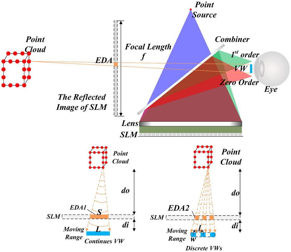
Figure 1 shows a diagram of the HHMD system and the computation reduction principle. The compact structure of this HHMD system refers to the Fourier transform optical system employed by Yoneyama et al.[9], which consists of only one point source, one spatial light modulator (SLM), and one lens located near the SLM, as shown in the upper part of Fig. 1. The lens has two functions: one is collimating the diverging wave from the point source and the other is converging the central diffraction wave from the SLM into a common area in a short view distance. In order to observe the real and virtual images at the same time, a half mirror as a combiner is located between the lens and the point source. With the Fourier transform optical system, the field of view (FOV) of the HHMD system can be enlarged, which now is not determined by the diffraction angle of the SLM, but is according to the width of the SLM and the focal length of the lens . The view angle of this system is given as
Sign up for Chinese Optics Letters TOC. Get the latest issue of Chinese Optics Letters delivered right to you!Sign up now
Figure 1.Structure of the HHMD system and the principle of computational reduction.
In conventional naked-eye holographic display, in order to achieve the largest view area, the wavefront of an object point the size of the full hologram should be calculated, as the observing eye is free to move. However, the HHMD differs from conventional naked-eye hologram display in that the hologram display is fixed in front of the eye at a short distance, which causes some of the wavefront produced by the conventional CGH to not be observed and wasted. Therefore, conventional CGH generation method has large redundancy for HHMD applications. Compared with our proposed method, only the part of the wavefront in the view area needs to be calculated. We call the region producing an effective wavefront in the hologram as the EDA for eyes. As the number of the wavefront sampling pixels decreases, the computed burden can be reduced. The EDA is defined according to the projection relationship. The EDA of each object point is determined by the intersection of the connection between the VW and the hologram display, as shown in Fig. 1. In theory, only the wavefront entering the pupil of an observing eye is effective, which means only a wavefront of the pupil size needs to be calculated. However, an eye will rotate and shift in a range, so an optimal practical EDA should make the eye receive a proper wavefront when moving in the range. Here, two types of EDA are proposed. The first type considers the moving range of an eye as the VW. The second type takes the pupil size of an eye into account and discretizes the moving range into several VWs. Only the diffraction information contributed to the VWs needs to be calculated.
With the first type of EDA, as shown at the bottom left in Fig. 1, the size of the EDA contributed by an object located at a distance is given as where is the distance between the eye and the hologram display, and is the moving range of the eye. In the HHMD, the position of the eye is relatively stable for the display. When the moving range is smaller than the length of the display, the calculation amount can be reduced. For each object point, the number of the pixel sampling its wavefront is , where is the pixel pitch of the display. In conventional CGH, the amount is the total pixel number of the display.
With the second type of EDA, the factor of the pupil size of an eye is added to further reduce the amount of the calculation. The reason for reducing the calculation amount is that an eye can rebuild the object when the pupil receives only a little wavefront information. It is also the reason why the light field display can offer a convergence cue by constructing several directions of light for an object point. The optimized sampled wavefront would guarantee the smoothness of the rebuilt object and at the same time the size as small as possible. To achieve the goal, the moving range is discretized into several equally spaced VWs, as shown at the bottom right in Fig. 1. If the width of each discrete VW is smaller than the central distance between two VWs, the calculation amount can be further reduced. The area between two adjacent VWs must be smaller than the near-diffraction-limited size of a normal eye (2 mm)[15]. With such a VW division method, the pupil of an eye will always lie in at least one VW. The number of discrete VWs is , and the number of sampling pixels needing to be calculated for an object point is . The ratio is used to measure the different sizes of the effective wavefront entering the observing eye.
Two proposed algorithms are carried out on a CPU and a GPU; the calculation times of CGHs with the conventional method and two types of EAD are compared. For CPU serial computation, the wavefront of each point is calculated in order. Since a complex value of each pixel in a hologram is the wavefront superposition of a plurality of object points, it causes the confliction of memory reading and writing for GPU parallel computation. To make these algorithms suitable for parallel computing, reading and writing on the same memory block simultaneously must be avoided. Figure 2 shows the improved program to do the GPU adaptability. Instead of calculating the wavefront of each object point, the GPU program simultaneously calculates the complex value of each hologram pixel. All the threads share the same memory block, which stores the position and intensity information of the object points. Different from the conventional CGH, a hologram pixel is the addition of the wavefront at the position of all the object points, and our proposed method needs the frustum to determine which object points contribute the complex value of a given hologram pixel. The vertex of the frustums is the given pixel, and VWs are the undersurfaces. Only the wavefront of the object points in the frustums is added to calculate the complex value of the given pixel.
Numerical simulation is carried out to test the reconstructed images from CGHs generated with the proposed method. Three sets of images are given to show the comparison of the calculation time for generating holograms with different methods. These generation algorithms are conducted both on a CPU and a GPU. We use Microsoft Windows 7 Professional Service Pack 1 as the operating system, a computer with an Intel Core i7-4770 processor of 3.4 GHz, memory of 8 Gbytes, and Microsoft Visual C++ 2009 as the language compiler. The GPU code is run on an Nvidia GeForce GTX660GPU board, using a combination of the high parallel programming architecture CUDA and a graphic API.
Figure 2.Parallel computing of the value of hologram pixels. The frustum setting determines the contributing object points.
The reconstructed results are shown in Fig. 3. The upper is the simulated observed images by an eye with pupil size 4.0 mm. The images are reconstructed from parts of a hologram of different sizes to simulate wavefronts of different sizes entering an eye. It can be shown that the reconstructed images from the first type of EDA recording method have few differences with those from the conventional method despite the reduction in the size of the wavefront. However, the quality of the reconstructed images from the second type decreases. The reason is that the pupil of the eye is larger than the size of the effective wavefront, which causes some invalid wavefronts to also be observed by the eye. The invalid wavefronts become noise in the reconstructed images, which results in a lower reconstructed quality. The peak signal-to-noise ratio (PSNR) between the reconstructed images from different CGH generation methods and the original images is calculated to evaluate the reconstructed quality. The generated time and the PSNR are shown at the bottom of Fig. 3. With the size of the calculated wavefront reduced, it takes less time to generate a hologram. For a 6.0 mm wide moving range, the generated time can be reduced to 15%–20% of the conventional generation method, with continuous VW and to 1.5%–10% with discrete VWs. Although the noise can be restrained by averaging multiple holograms[16], it obviously will consume additional computational resources. Fortunately, the following optical experiment shows that the noise has a weak influence on the observation.
Figure 3.Numerical simulation. Upper: reconstructed images from the three algorithms. The resolution of the images (can be regarded as the number of the object points): macaroon (), rabbit (), and clown (). Bottom: calculated time (CPU and GPU) of generating the hologram from the three algorithms and the PSNR of the reconstructed images.
An HHMD system is set up to verify the proposed EDA recording method. A photograph of the constructed experimental system is shown in Fig. 4. A reflection-type phase modulating SLM is employed to load the CGH. The size of the SLM in the system to produce the target wavefront is 0.7 in. with a pixel size 8.0 μm. It is illuminated by a parallel light whose wavelength is 625 nm from a red LED settled in the focal point of a lens with a focal length of 80 mm. The observing eye is located at the focal length of the lens. The FOV of the system is about following Eq. (2). The FOV can be broadened by using a larger numerical aperture lens. In order to realize a full-color HHMD system, the light source can be replaced by three red, green, and blue LEDs. Simultaneously, a time division multiplexing system should be adopted to avoid chromatic aberration.
The 3D modeling software 3DMax is used to render a texture image and a depth image of a 3D scene. Two images are combined to determine the spatial positions of the object points of the 3D scene. In our experiment, the size of the two images is , which means that they can represent points. In the experiment, a rabbit is set at 0.5 m from the SLM and a dragon is set at 1.5 m. In the first type of EDA recording method, the VW is set to be 6.0 mm wide, which is also the moving range of an eye. The width of each VW is set to be 1.5, 1.3, 1.0, and 0.8 mm wide in the second type of EDA recording method to test the quality of the reconstructed images from wavefronts of different sizes entering the pupil of an eye. With the conventional CGH generation method, for each object point it needs times to calculate its wavefronts, while the number can be reduced to about 15% with the first type of EDA recoding method and 1.5% with 0.8 mm wide VWs with the second type.
The CGH calculation time spent by three methods on the CPU and GPU can be shown in Table 1. The calculations on the CPU used only a single CPU thread. The acceleration results are in accord with the above analysis. Figure 5 shows the optically reconstructed images from the CGHs generated by the proposed method. In the experiment, the central distance between two VWs is set to be 2 mm and the reconstructed results with different widths of VW are tested. The experiment is presented in an augmented virtual reality way. A real cup is at the same distance as the virtual rabbit and the depth of a real cube is identical to the virtual dragon. These photographs are captured with a Canon EOS 60D digital camera with a 50 mm lens at to imitate a normal human eye. The camera is focused on 0.5 and 1.5 m separately to capture the two reconstructed models. When the nearer objects (cup and rabbit) are focused by the camera, the farther objects (cube and dragon) are blurred, as shown in Fig. 5(a). On the other hand, when the farther objects are focused, the nearer objects get blurred, as shown in Fig. 5(b). Moreover, the reconstructed objects with the conventional method and with the first type of EDA recording method are nearly the same, which means the result observed by an eye is not influenced by the wavefront produced by the non-effective diffraction area. In addition, although less wavefronts are received by the pupil of an eye with the second type of EDA recording method, the models can be reconstructed successfully with a little decline in the smoothness. Although numerical simulation indicates that the second type EDA recording method leads to a poor reconstruction, the experiment illustrates that the human eye is not sensitive to the noise. Compared to the significant decrease in the calculated amount, the slight decline in the quality of reconstruction is an acceptable tradeoff.
Figure 5.Optically reconstructed images. (a) The nearer objects are focused, and (b) the farther objects are focused.
In conclusion, a simple and fast CGH generation method for the HHMD by the EDA recording method is presented. The proposed method dramatically reduces the computational burden in the conventional generation methods.