1Department of Electronic Engineering, Shanghai Jiao Tong University, Shanghai 200240, China
2Key Laboratory for Laser Plasmas (Ministry of Education), Department of Physics and Astronomy, and Collaborative Innovation Center of IFSA (CICIFSA), Shanghai Jiao Tong University, Shanghai 200240, China
Zhicheng Ye, Jun Zheng. Wide range bilayer aluminum nanowire grating sensors with robust reflective peaks[J]. Chinese Optics Letters, 2020, 18(5): 052401
Copy Citation Text
A grating-coupled surface plasmon resonance sensor based on bilayer aluminum nanowire arrays is fabricated by laser interference lithography. The device presents impressive reflective sharp peaks by lateral surface plasmon resonances even for aluminum thicknesses of merely several nanometers. Distinct reflective peaks and dramatic color shifts under different analytes are observed within a wide range of incident angle, metal thickness, and refractive index. The sensitivity of 307 nm per refractive index unit is experimentally obtained. The reflective-peak-type surface plasmon resonance sensors are suitable for practical applications because of easy fabrication, low cost, wide range, and high signal visibility.
Attributed to the unique advantages of high sensitivity, label-free, and real-time, surface plasmon resonance (SPR) is broadly utilized as a sensing technology[1,2] in biomedicine[3–5], food security[6], environmental monitoring[7], and molecular recognition[8]. Generally, the mechanisms of SPR sensing can be divided into localized SPR and non-localized SPR. The localized SPR is attributed to the ultra sensitive electromagnetic resonance of metallic nanostructures like particles, rods, and lines, which are often attached in optical waveguides and fibers[9]. Non-localized SPR has the advantages of easy large scale fabrication and high uniformity, which is often excited via movement compensation: one is based on dielectric prisms, where the momentum required to excite SPR is supplied by the high refractive index prisms in total internal reflection; the other is grating type, where the excitation of SPR is realized by the diffraction effect[10,11]. In practical applications, prism-based SPR sensors are cumbersome and complicated in configurations, while the grating-based sensors have the advantages of slimness, compactness, and flexibility for operation.
So far, in SPR sensors including both the dielectric prisms and unilayer gratings types, surface plasmons are excited on the metal/analyte interface away from the incident plane, which leads to narrow ranges of incident angles or ambient refractive index[12] for maintaining sharp reflective dips. As the incident angle, wavelength, or refractive index deviates from the design values[13–15], the dips are dramatically broadened, leading to the decrease of sensing accuracy.
In this work, an SPR sensor based on a bilayer metallic grating was proposed, where plasmonic polaritons were excited on the interface between the bilayer metallic grating and the analyte in the incident plane, which resulted in sharp reflective peaks. Both the simulations and experiments prove that these SPR peaks remain sharp under a wide range of incident angle, metal thickness, and refractive index, which present high signal visibility. The metallic gratings were fabricated by laser interfere lithography and then coated with aluminum (Al), which is suitable for mass production. All of these high performance characteristics of the bilayer Al grating contribute to a robust sensor with large process tolerance and low fabrication cost.
Sign up for Chinese Optics Letters TOC. Get the latest issue of Chinese Optics Letters delivered right to you!Sign up now
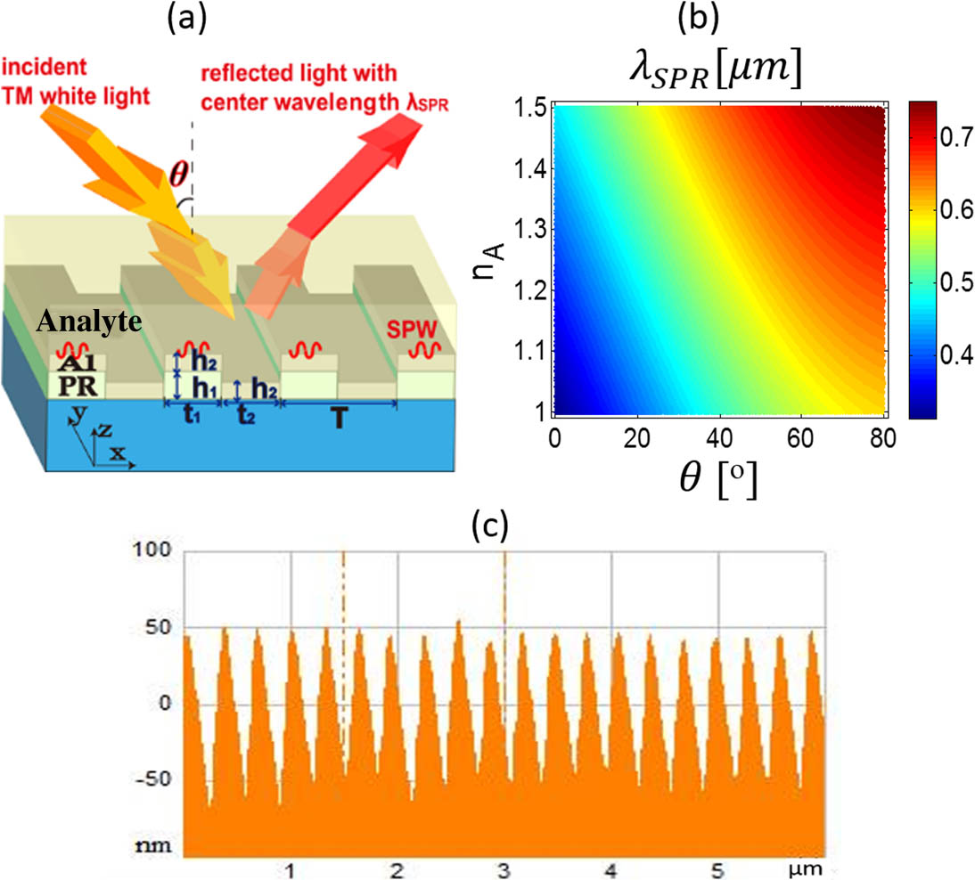
The schematic of the bilayer Al nanowire grating is illustrated in Fig. 1(a). The transverse magnetic (TM) polarized light is incident on the grating through the analyte and is reflected with a single peak of wavelength . Figure 1(c) shows the atomic force microscope (AFM) image of a fabricated device. The photoresist (PR) grating with pitch , PR line width , and thickness was fabricated by laser interference using a He–Cd laser (442 nm, Kimmon Laser) with cross angles of 94.6°. The grating was then coated with an Al film of thickness by electron beam evaporation. The duty ratio of the bilayer Al grating is .
Figure 1.(a) Schematic diagram of the bilayer metallic nanowire grating. (b) The theoretical SPR wavelength changing with ambient refractive index and incident angle . (c) AFM image of the fabricated grating structure.
The SPR excited on the interface between Al grating and analyte obeys the following equation[16,17]: where is the reciprocal lattice of the grating. and are the wave number and incident angle of the light in the analyte, respectively, which is directly incident to the grating. By Snell’s law, , where and are the wave number and incident angle in vacuum, respectively, as shown in Fig. 1(a). Thus one can get
The wave number of SPR is where is the refractive index of the analyte covering the surface of grating, and is the permittivity of Al described by Lorantz–Drude’s model[18]. The propagation direction of the surface plasmon wave (SPW) is along the direction. Figure 1(b) shows the SPR wavelength changing with the incident angle and the analyte refractive index . Considering that the absolute value of the permittivity of Al in visible light is considerably larger than , the resonance wavelength can be deduced as
Thus, the sensor sensitivity, i.e., wavelength shift per refractive index unit (RIU), is . It means that the larger period is, the higher the sensitivity of the wavelength shift per RIU is; meanwhile, the larger resonance wavelength is required. In experiments, the incident angle can be changed to get the sharpest resonant peaks. The simulated reflective spectra with and grating pitch by using rigorous coupling wave analysis (RCWA, DiffractionMode, Rsoft) are shown in Fig. 2(a1), where the sharp reflective peaks shown with the black dashed line agree well with the theoretical results calculated by Eq. (4). The magnetic field , which shows the SPW excited on the interface between Al and the analyte for wavelength and incident angle , is presented in Fig. 2(a2).
Figure 2.Simulated reflective spectra of the grating in ambient conditions. (a1) Reflected spectra changing with incident angle . (a2) The magnetic field of the resonant peak for and . (b1), (b2) Simulated reflected spectra changing with duty ratio with for bilayer and unilayer Al gratings. (c1), (c2) Reflected spectra changing with PR thickness and Al thickness with incident angle for bilayer Al grating. Other parameters are the same as that in Fig. 1.
The influences of the duty ratio on the width of the SPR peak are shown in Figs. 2(b1) and 2(b2) for the bilayer Al grating and unilayer Al grating, respectively. For obtaining narrow and high reflectance SPR peaks, should be 0.2–0.5 and 0.3–0.6 for bilayer and unilayer structures, respectively. Clearly, the SPR peaks of the bilayer structure are narrower by about 20 nm than that of the unilayer case, meaning higher accuracy for sensing.
Figures 2(c1) and 2(c2) represent reflected spectra changing with thickness of PR and Al , respectively, where the center wavelength and narrow width of the resonance peaks keep existing values for and , showing robustness to the fabrication tolerance. The simulated reflected spectra of the grating under different ambient refractive indices are shown in Fig. 3. The dashed line of the calculated by Eq. (4) agrees well with the simulated reflected peak.
Figure 3.Simulated reflective spectra under different ambient refractive indices . The dashed line is the theoretical changing with . Other structure parameters are the same as that in Fig. 1.
The measurement setup is shown in Fig. 4(a). The gratings with wires perpendicular to the platform are stuck on one inner side of a cuvette’s chamber fixed on an auto-rotation platform. A collimated white light beam, polarized by a Glan–Taylor prism, is incident to the chamber with the electric field vertical to the grating lines. The reflected light is collected by an optical fiber with diameter of 100 μm and is detected by a spectrometer. Three kinds of ambient dielectric media including air, deionized water, and 80% sucrose solution are used in experiments. The reflections with are shown in Fig. 4(a), whose color is olivine, purplish red, and blue in ambient air, water, and sucrose solution, respectively.
Figure 4.(a) Snapshot of the measurement setup and the reflected photos with of white light in ambient air, deionized water, and 80% sucrose solution, respectively. (b1)–(b3) Measured reflective spectra with ambient air, deionized water, and 80% sucrose solution, respectively. The black dashed lines are the calculated by Eq. (4). (c) Refractive index calculated by Eq. (4). The horizontal lines are the average values.
The measured reflected spectra for air, deionized water, and sucrose solution are shown in Figs. 4(b1)–4(b3), respectively. The black dashed line in each figure is the theoretical , which is shifted with the incident angle and refractive index . The full width at half-maximum (FWHM) of the reflective spectra remains at about 30 nm, presenting the advantages of a wide working range of incident angles and wavelengths. The calculated average sensitivities are 307 and 350 nm/RIU from Figs. 4(b1) and 4(b2) as well as 4(b3) and 4(b1), respectively. The difference between the experimental and theoretical sensitivities comes from the error of measurement and the of the fabricated Al gratings being different from the theoretical one. From Eq. (4), we can deduce the refractive index, which is shown with points in Fig. 4(c). The horizontal lines are the average values, which are 1.015, 1.357, and 1.519 for air, deionized water, and 80% sucrose solution, respectively. Compared with the standard values of 1, 1.332, and 1.476[19], the measurement error is 1.5%, 1.9%, and 3.0%, respectively.
In conclusion, based on bilayer metallic nanowire gratings, metal thickness insensitive and wide working range grating-coupled SPR sensors were proposed and demonstrated, which produce sharp reflective peaks. The SPR peaks are red-shifted dramatically as the ambient refractive index increases; meanwhile, the profile of the peaks remains sharp within a wide range of refractive indices of analyte and incident angles. The easy fabrication and robust performance of the ultra-thin bilayer structure metallic nanowire sensors make the practical tests more convenient and lower cost.
Zhicheng Ye, Jun Zheng. Wide range bilayer aluminum nanowire grating sensors with robust reflective peaks[J]. Chinese Optics Letters, 2020, 18(5): 052401