1Key Laboratory of Wireless-Optical Communications, Chinese Academy of Sciences, School of Information Science and Technology, University of Science and Technology of China, Hefei 230026, China
2Shenzhen Graduate School, Tsinghua University, Shenzhen 518055, China
Kun Wang, Chen Gong, Difan Zou, Xianqing Jin, Zhengyuan Xu. Demonstration of a 400 kbps real-time non-line-of-sight laser-based ultraviolet communication system over 500 m[J]. Chinese Optics Letters, 2017, 15(4): 040602
Copy Citation Text
We extend the transmission range of non-line-of-sight ultraviolet communication to 500 m in a real-time system experiment using a 200 mW solid-state 266 nm laser, where the data rate can reach 400 kbps at a frame error rate lower than in the real-time system test. The results can beat the best record so far, in terms of both the data rate and transmission distance.
Due to scattering events in the ultraviolet (UV) spectrum in the atmosphere, UV optical wireless communication does not require perfect alignment of the transmitter and the receiver. It can also maintain the communication link with certain data rates in the case of blockage of the line-of-sight link. UV communication was first investigated using a mercury lamp as the transmitter along with an external modulator[1]. However, the drawback of a mercury lamp lies in high power consumption (500 W input power) and fragility, which impede the application in a wider range. Such an issue can be mitigated by using a UV LED or solid-state laser as the transmitter. Recently, non-line-of-sight (NLOS) UV optical communication using a UV LED as the transmitter has gained a lot of interest[2–4]. The NLOS UV channel has been extensively studied, both in the analytical aspect and in the experimental aspect[2–8].
Given that the path loss is very large for the NLOS UV channel, the detected signals at the receiver are extremely weak. Based on the weak signal characteristics, in existing works the photon-counting receiver is adopted to detect the photoelectrons in the real-time NLOS UV system[8,9], where the transmission range was limited to within 100 m at a data rate of several kbps. Moreover, multiple signal processing approaches were employed[10,11]. Even though diversity reception technology was employed, the reported transmission range remained less than 100 m[11].
A more fundamental and interesting topic is to extend the transmission range of the NLOS UV communication. Long distance channel measurement experiments have been reported in recent works[2,3]. Based on the measurements, it was predicted that the data rate could reach 100 kbps at a range of 2000 m[2,3]. However, there is still no report on a real-time NLOS communication system with a data rate beyond 10 kbps over a distance beyond 100 m in existing literature.
Sign up for Chinese Optics Letters TOC. Get the latest issue of Chinese Optics Letters delivered right to you!Sign up now
In this work, we extend the NLOS UV communication range to 500 m using a UV laser as the transmitter with a small divergence angle less than 0.8 mrad and a single photon-counting block as the receiver. We design the receiver-side signal processing approaches based on the Poisson distribution assumption for the detected photoelectron numbers. Computer-based simulation was carried out to evaluate the system performance. We also realized a real-time UV communication system, with both optical devices and electrical baseband processing implementation in the hardware. In the experiments, we first conducted an outdoor measurement for the NLOS UV channel, which verified the Poisson distribution assumption. We also conducted an outdoor real-time communication experiment for a transceiver distance up to 500 m, where the data rate can reach 400 kbps at a frame error rate (FER) below .
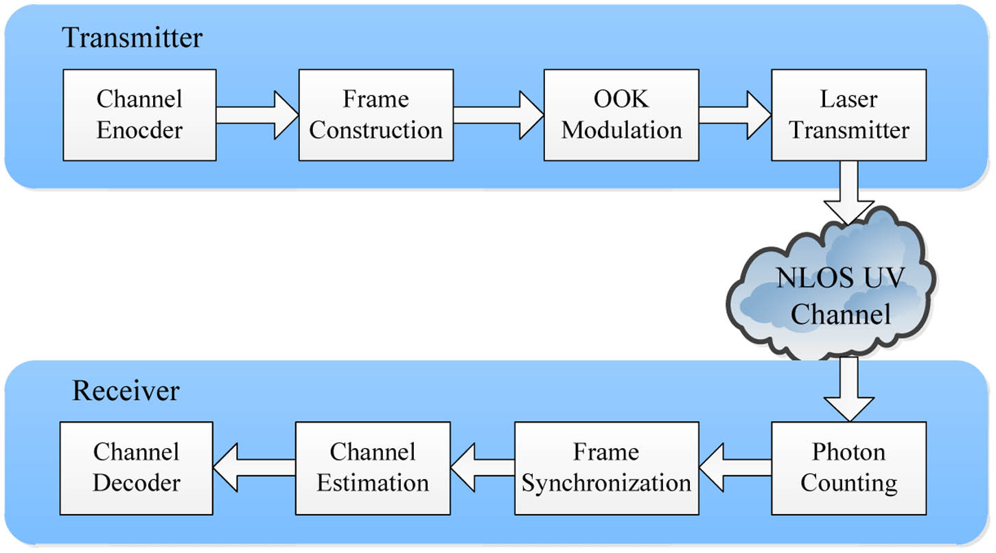
A block diagram for the NLOS UV communication system is shown in Fig. 1. At the transmitter side, the information bits are first encoded by the channel encoder. A concatenated code is chosen for the forward error correction (FEC) code, which consists of a (63, 47) Reed–Solomon (RS) code as the outer code and a (3, 1, 3) convolutional code as the inner code. The entire code rate of the concatenated code is around 24.7%. Then, the coded bits are divided into transmission frames and the synchronization codes are added in front of each frame and are used for both frame synchronization and channel parameter estimation at the receiver side. Each transmission frame contains 1204 bits, which consist of 64 synchronization bits and 1140 coded bits. There are 282 information bits to be coded in each transmission frame. The transmission frames are further modulated into on-off keying (OOK) symbols, which drive the external modulator to modulate the UV laser transmitter.
Figure 1.Block diagram for the NLOS UV communication system.
Due to the weak signal for the NLOS UV communication up to several hundreds of meters, the detected signals at the receiver side can be characterized by discrete photoelectrons[8,9]. For the OOK modulation scheme, the number of detected photoelectrons in each symbol slot satisfies the Poisson distributions[8]where denotes the on OOK symbol and denotes the off OOK symbol, and and denote the mean numbers of detected photoelectrons for the signal components and the solar background radiations, respectively. For a given symbol rate , link gain , and transmission power , can be expressed as where and denote Planck’s constant and the frequency of the optical signal, respectively, and denotes the quantum efficiency of the detector.
At the receiver side, a photon-counting unit is employed to count the number of photoelectrons in each symbol duration. Frame synchronization is then performed to find the start of each transmission frame based on the slicing-based approach[12]. The synchronization sequences can also be utilized to estimate the channel parameters and . Let denote the transmitted synchronization symbols. We define two data sets and , which include the detected photoelectron numbers corresponding to synchronization symbols and , respectively. Then, the maximum likelihood (ML) estimates of and are given as where and denote the sizes of sets and , respectively. Based on the estimated channel parameters, the log likelihood ratio (LLR) of the detected photoelectron number can be expressed by Soft-decision decoding is applied to the FEC decoding to extract the information bits based on the LLR information. More specifically, the soft LLR information is applied to the decoding of the inner convolutional code. The decoded bits are further decoded by the outer RS code.
Computer-based simulations were carried out to evaluate the system performance. Relevant parameters in the simulations are shown in Table 1. They follow the specifications of the equipment in the real system. Based on the measurement for the NLOS UV channel[2,3], the path loss for a 500 m distance is approximately 100 dB at a 10° transmitter elevation angle and 30°receiver elevation angle. The corresponding link gain is . Based on Eq. (2), the mean number of photoelectrons in this geometry is only around 1.1. For a smaller transmitter and receiver elevation angle pair, the link gain would have an increase, which leads to the increase of . Therefore, we set in the range from 1 to 10 in our simulation. The synchronization performance for three different levels of background radiation is shown in Fig. 2. It is seen that even for the strong background radiation condition , the miss synchronization probability is lower than when is greater than 6. The bit error rate (BER) performance is shown in Fig. 3. It can be seen that the BER becomes lower than as the signal component is greater than 6. The results indicate that the NLOS UV communication link for the 500 m transceiver distance is achievable for a small transmitter and receiver elevation angle pair.
Figure 2.Miss synchronization probability from computer-based simulations.
We realize a UV communication system consisting of bothoptical devices and electrical signal processing in the hardware. On the transmitter side, a 266 nm UV laser with a 200 mW constant optical power and less than 0.8 mrad divergence angle was deployed 500 m away from the receiver. The communication test bed realization is shown in Fig. 4. The angle between the transmission direction and the direction pointing to the receiver was approximately 0.02 rad. For a transceiver distance of 500 m, the 0.02 rad pointing angle corresponded to 10 m distance from the receiver to the optical light, which guarantees no line-of-sight component at the receiver. Larger pointing angles denote larger distances between the receiver and the optical light. At the receiver side, a HAMAMATSU PMT (R7154 module) detector was employed to convert the optical signals to the electrical signals. The PMT was equipped with a narrow UV optical filter that blocked the solar radiation out of the deep UV band. The output of the PMT was amplified by a customized circuit and then converted into digital signals by an analog-to-digital converter (ADC) module with a sampling rate of 100 Msps. The photon-counting unit was realized on a field-programmable gate array (FPGA) board based on the rising-edge detection on the digital output of the ADC module.
Figure 4.NLOS UV communication test bed at (a) the transmitter side and (b) the receiver side.
We first conducted a channel measurement experiment to verify the Poisson distribution assumption of the photon-counting outputs within a certain slot. Based on the experimental data, the probability density function (PDF) for the detected photoelectron numbers can be well approximated by the Poisson distribution. This validates the baseband signal processing based on the assumption of the Poisson distributed detected photoelectron.
We also carried out a field test for the real-time NLOS UV communication system. The transmitter and receiver were placed within two buildings at a distance of 500 m. The signal processing parts at the transmitter side, such as channel coding and modulation, were realized on a Xilinx Spartan-6 FPGA board. 0–1 randomly generated information bits were first encoded by a 24-bit cyclic redundancy check (CRC) code for error detection at the receiver. The OOK modulated signal from the FPGA board was used to drive the external acousto-optic laser modulator, which changed the direction of the output laser. A board with a hole was placed in front of the modulator, such that the laser direction for OOK symbol 1 could pass through the hole but the laser direction for OOK symbol 0 could not. The symbol rate of the system was set to 2 Msps. Due to the FEC code rate and the overhead of the synchronization sequences, the rate of the information bits was about 400 kbps. At the receiver side, a PMT was employed to detect the optical signals. The detected signals from the PMT are the discrete photoelectrons, which are shown in Fig. 5. The negative pulses in the figure denote the photoelectron signals with a time duration of 10 ns for each pulse. Since the pulse duration is 10 ns, as shown in Fig. 5(b), the sampling rate of 100 Msps is required to capture the pulses. The output of the PMT was amplified and then converted into digital signals. Then, the digital output was sent to the photon-counting unit based on the rising-edge detection on the FPGA board. Further signal processing parts, such as frame synchronization, channel estimation, and channel decoding, were carried out on the FPGA board based on the output of the photon-counting unit. In real experiments, for transmitted data frames, there was no miss synchronization event; and only 8 frames did not pass the CRC check, which leads to the FER below . Note that the reason for achieving the 400 kbps data rate lies in the small scattering angle of 0.02 rad. The data rate would decrease as the scattering angle increases.
Figure 5.Detected photoelectron signals: (a) multiple electrical pulses and (b) single electrical pulse.
In conclusion, we demonstrate the system design and hardware implementation for the NLOS UV communication over several hundreds of meters. Outdoor experiments show that the transmission range can reach 500 m at a data rate of 400 kbps and an FER below . A higher data rate can be achieved if the concatenated convolutional and RS codes are replaced by more capacity-approaching codes, such as the low density parity check codes. This is planned for our future work.
References
[1] J. J. Puschell, R. Bayse. Proceedings of the Tactical Communication Conference, 253(1990).
Kun Wang, Chen Gong, Difan Zou, Xianqing Jin, Zhengyuan Xu. Demonstration of a 400 kbps real-time non-line-of-sight laser-based ultraviolet communication system over 500 m[J]. Chinese Optics Letters, 2017, 15(4): 040602