Abstract
We demonstrate both experimentally and theoretically the trapping and guiding of a weak signal pulse via a self-accelerating Airy pulse. This is achieved by launching the Airy pulse in the anomalous dispersion regime of an optical fiber, thereby inducing a gravity-like potential that can compel the signal pulse in the normal dispersion regime to undergo co-acceleration. Such guiding pulse by pulse can be controlled at ease simply by altering the acceleration conditions of the Airy pulse. Furthermore, the guided signal can be featured with either single or double peaks, which is explained by using the theory of fundamental and second-order quasi-modes associated with the gravity-like potential. Our work represents, to our knowledge, the first demonstration of pulse guiding in the anomalous dispersion regime of any self-accelerating pulse.1. INTRODUCTION
An intense pulse can create a barrier in optical fibers through which another probe pulse with a comparable group velocity cannot pass [1]. Such a phenomenon, as a fiber-optical analog of the event horizon [2,3], is useful for all optical signal processing and has been proposed for a variety of applications, including highly coherent supercontinuum generation [4], solitonic cavity [5,6], rogue wave control [7], compensation of the soliton self-frequency shift [8], and ultrashort pulse generation [9]. Meanwhile, rich phenomena are also brought about with the acceleration of the pump (generally a soliton) pulse that can induce a gravity-like potential. It has been demonstrated that an accelerating soliton is able to trap or periodically reflect a probe pulse [10–12], which is the key reason for the blue part of the supercontinuum. Such an acceleration can be induced by the effect of soliton self-frequency shift. In the absence of Raman scattering, the soliton trajectory can be altered by the probe signal, which in turn has an influence on the probe [13–15], or by changing the longitudinal dispersion of the fiber [16]. Unfortunately, the accelerations realized in these ways are rather difficult to reconfigure in both sign and magnitude. Recently, a self-accelerating pulse, namely, Airy pulse [17], has attracted a great deal of attention. A variety of applications have been demonstrated by employing such pulses, including, for instance, light bullet generation [18,19], nonlinear process control in optical fibers [20–23], nanomachining optimization [24], and soliton manipulation [25]. Quite recently, these accelerating pulses have been employed to control the optical Cherenkov radiations [26,27]. This is partly due to acceleration of the Airy pulses being simply altered by using the initial conditions associated with their spectral phase, thus capable of bringing about reconfigurable accelerating potentials to control a light signal. Just as their spatial counterparts (i.e., Airy beams), which have been employed for light control with light [28,29], the implementation of Airy pulses for controlling other pulses is still in its infancy. Recently, numerical simulations have shown that Airy pulses in the normal dispersion regime can be used to trap and guide a signal in the anomalous dispersion regime of optical fibers [30]. However, an Airy pulse in the anomalous dispersion regime and its induced gravity-like potential have not been used for signal trapping because, thus far, it has been thought that it would destabilize the dynamics of the signal pulse [30].
In this work, we demonstrate both experimentally and theoretically the trapping and guiding of a weak signal in the normal dispersion regime via an Airy pulse in the anomalous dispersion regime. The signal can be trapped and then enforced to undergo co-acceleration with the Airy pulse. Such guidance is reconfigurable by altering the acceleration of the Airy pulse in terms of its sign and amplitude. The guided signal is featured with either single or double peaks, which is further explained by using the theory of quasi-eigen modes of such accelerating potentials.
2. RESULTS
In experiment, the guiding effect for an accelerating potential is studied in a dispersion shifted fiber (DSF) whose zero-dispersion wavelength is around 1547.7 nm. The experimental setup is schematically plotted in Fig. 1(a). An Airy pulse and a weak signal pulse, trimmed from the same femtosecond laser via a pulse shaper, can be modulated to have the same group velocity by properly choosing their center wavelengths, and their spectra can be located in the regions of anomalous dispersion and normal dispersion, respectively [Fig. 1(b)].
Sign up for Photonics Research TOC. Get the latest issue of Photonics Research delivered right to you!Sign up now
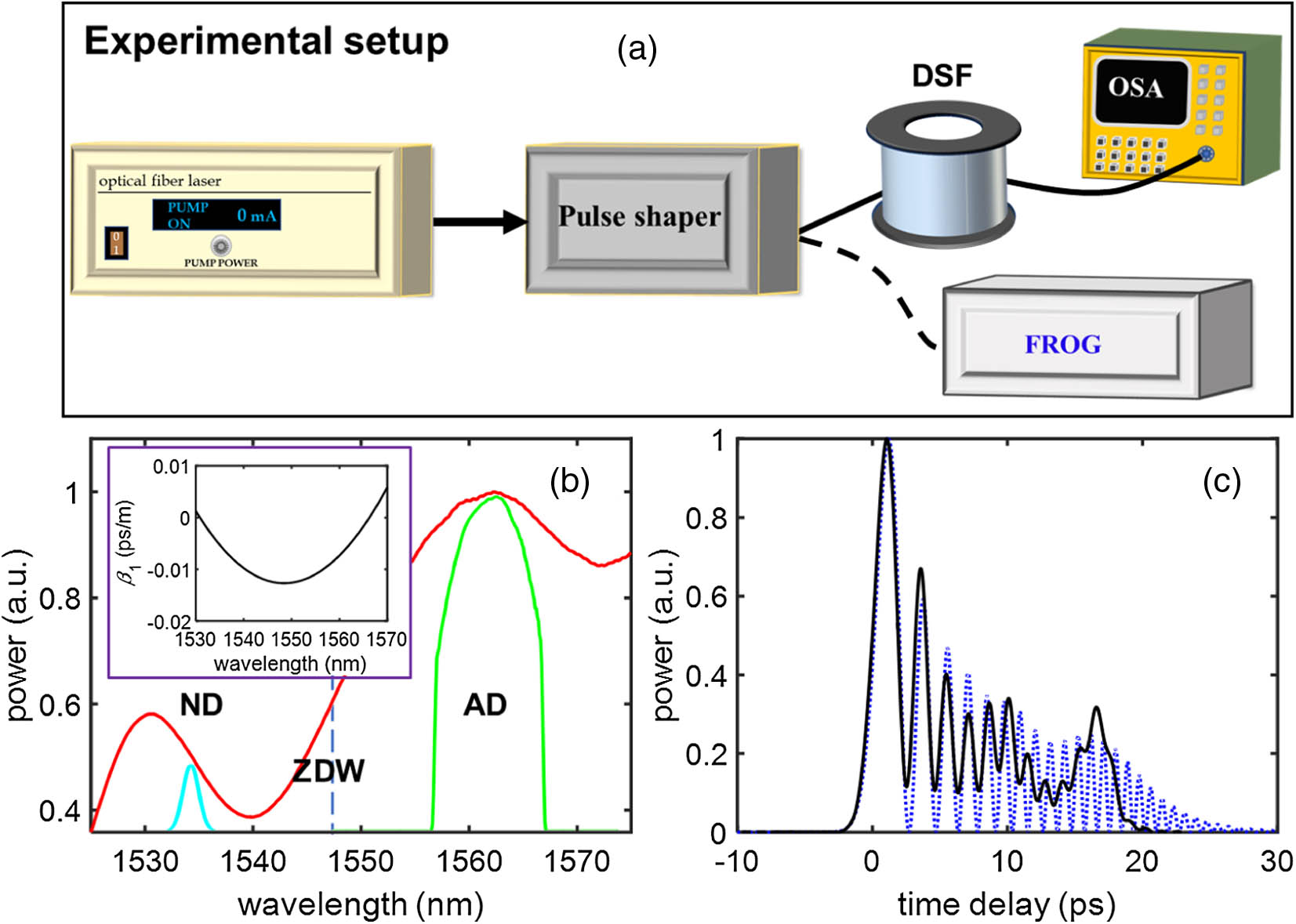
Figure 1.(a) Schematic of the experiment setup. (b) Measured spectra of an Airy pulse (green) and a signal (cyan), trimmed from a femtosecond laser pulse of a broad band (red), where the vertical dashed line marks the zero-dispersion wavelength (ZDW). The inset shows the relative group delay of the DSF we used in experiment. (c) Experimental measurement (black) and numerical simulation (blue) of the input profiles of an Airy pulse with .
In order to realize an intense Airy pulse for our study, we used a bandpass of a rectangle shape (between 1558 and 1568 nm). Because the cubic phase (wrapped between 0 and ) tends to introduce an attenuation due to the resolution limit of the pulse shaper, the resulting spectrum shows a deviation from the original one in this band. Right following the pulse shaper, the two pulses copropagate in a 4 km long DSF. At the output, an optical spectrum analyzer (OSA) is used to measure their spectra. The Airy pulse is produced by employing a cubic spectral phase formulated as (where is the angular frequency, is the center angular frequency, and is the modulation depth). Its temporal profile as measured by a frequency resolved optical grating (FROG) system from Mesa Photonics is shown in Fig. 1(c), where the discrepancy between the measurement and the numerical calculation is caused by reduced measurement accuracy of the FROG system for a complex pulse shape. Before the pulse guiding experiment, we carefully turned up the input power of the Airy pulse to a sufficiently high level (0.9 mW) to induce a considerable nonlinear index change under the Kerr effect but right below a threshold power to avoid the advent of Cherenkov resonance radiation [26] or soliton self-frequency shift [20] when it propagates alone. Then a signal of a Gaussian-like shape is employed to probe the Airy pulse-induced potential. The probe pulse’s input power is kept at a low level to avoid the influence of any nonlinear effect induced by itself. In the spectral domain, it is imposed by a linear phase term [i.e., , where is a constant] to adjust its temporal location compared with the Airy pulse. Under the action of the accelerating potential, the spectrum of the signal varies differently at the output when adjusting the value of , as summarized in Fig. 2(a). In most cases, the spectrum has a small shift. However, when the time delay of the signal is close to zero, the spectrum of the signal pulse experiences a quite large conversion (i.e., shifts to ). To have a better understanding of the experimental results, we perform simulations by using the following equations with parameters similar to the experimental conditions [31]: where and are the field envelopes of the Airy and the signal pulses, respectively, (or ) is the propagation distance along the fiber (or the time delay), and () and () are the coefficients of the corresponding second-order dispersion. Approximately, both pulses have the same value for the nonlinear coefficient () and the third-order dispersion ().

Figure 2.Trapping and guiding of a weak signal pulse of Gaussian-like shape via a nonlinear Airy pulse. (a) Experimental measurements of the wavelength conversion for the signal with different initial time delays. (b) Numerical simulations corresponding to (a). (c)–(f) Simulations of propagation dynamics for (c) the Airy pulse and (d)–(f) the signal pulse corresponding to three different initial time delays marked by D, E, F in (b) and (c). The white dotted lines in (c)–(f) are added to trace the main lobe of the Airy pulse.
The simulated output spectrum of the signal upon different time delays controlled by the value of is shown in Fig. 2(b), which reproduces the measurement in Fig. 2(a). Under the action of the Airy pulse, whose nonlinear propagation is shown in Fig. 2(c), signal pulses of different initial time delays are presented in Figs. 2(d)–2(f), corresponding to different propagation scenarios. When the time delay is zero, most of the signal is trapped and guided by the accelerating potential from the beginning [Fig. 2(d)]. Thus, the trapped signal experiences acceleration throughout the propagation and, consequently, gains a maximum spectral shift (indeed the spectrum changes correspond to velocity changes caused by acceleration). If the signal is positioned ahead of the Airy pulses at the input, it propagates freely within a certain distance, until the accelerating Airy pulse catches up with it and then pushes it to accelerate [Fig. 2(e)]. Such a short distance of acceleration leads to only a small range of wavelength conversion. For the third case, shown in Fig. 2(f), the sublobes of the Airy pulse attempt to push the signal to accelerate, but the influence is only marginal; thus, the resulting spectrum change at the output is not noticeable. Soliton shedding is noticed in Fig. 2(c) [23]. In order to produce better accelerating potential, one may employ an Airy pulse in the normal dispersion to avoid the soliton formation. But the resulting self-defocusing effect tends to cause a reduction of the peak power in the Airy main lobe, which has a negative impact on signal trapping. Our additional simulations (not presented here) show that the Airy pulse in the normal dispersion regime indeed fails to improve the signal trapping/guiding.
Next, we fix the time delay of the signal to be zero (i.e., by letting ) and use signals of different bandwidths to probe the accelerating potential. While keeping the center wavelength (i.e., 1534 nm) unchanged, the FWHM of the signal’s spectrum varies from 2.08 down to 0.98 nm, corresponding to the pulse duration (characterized by the FWHM) changing from 1.67 to 3.53 ps. Although the signals have different pulse widths at the input, their trapped parts measured at the output (already shifting to ) exhibit similar shapes [Fig. 3(a)]. The experimental results are further reproduced by the numerical simulations shown in Fig. 3(b). By means of the simulations, one can visualize temporal distribution of the signal at the output. The trapped parts for all the cases show similar features in terms of time delay and pulse duration under the guiding effect of the Airy pulse [Fig. 3(c)]. This indicates that the accelerating potential may favor and support specific modes, and the part that does not match its “guided” mode cannot be trapped and routed. In contrast, if the Airy pulse is absent, the signals at the output are not temporally shifted and exhibit a much wider pulse width, particularly for the initial condition of shorter pulse duration [Fig. 3(d)].
Figure 3.Spectral (upper row) and temporal (bottom row) outputs of the signals with different input pulse durations. (a) Experimental measurements in the presence of the Airy pulse. (b)–(d) Numerical simulations using the experimental parameters associated with (a), but in (d) the Airy pulse is assumed to be absent.
In the following, we study how to control the signal routing by shaping the Airy pulse. As a typical example, the signal pulse employed in Fig. 2 is used. Such control can be performed simply by changing the parameter in the cubic spectral phase associated with the Airy pulse. First, the sign of the cubic phase term is reversed (i.e., ), leading to a decelerating Airy pulse. Using a similar way to obtain the results in Figs. 2(a) and 2(b), the spectral changes of the signal at the output in experiment and simulation are shown in Figs. 4(a) and 4(b), respectively. The spectral patterns are horizontally reversed with respect to the case of but not in a mirror-symmetric manner mainly caused by the third-order dispersion. Now one can notice a considerable blueshift when the time delay of the signal is around zero, which is induced by the trapping and guiding effects of the accelerating potential. Second, we employ different values of to control the signal guiding while using the same time delay (i.e., by always letting ) for the signal. Figure 4(c) summarizes the corresponding results. With the increase of the value of , the (absolute) acceleration of the Airy pulse decreases and so does the (absolute) acceleration of its trapped signal, leading to a reduced spectral shift. The experimental results have a good agreement with the numerical simulations, as shown in Fig. 4(d).
Figure 4.Experimental measurements (left column) and numerical simulations (right column) on the control of the signal guiding by using reconfigurable accelerating potentials. Upper row has the same description with Figs. 2(a) and 2(b) but with an opposite acceleration sign. Bottom row shows the output spectra of the signal pulse driven by the control pulse of different accelerations while keeping near-zero time delay of signal.
Inspired by that a conventional (straight) spatial waveguide can support higher-order as well as fundamental modes, we attempt to employ the accelerating potential to trap and guide multipeak signals. As a typical example, the Airy pulse in Fig. 2(c) is under test and our simulation shows that its induced accelerating potential can indeed guide a double-peak signal [Fig. 5(a)]. Referring to the calculation, we design a signal having the spectral shape shown in Fig. 5(b). After propagation for 4 km in the fiber in the presence of the Airy pulse, such a signal still preserves its double-peak feature while exhibiting a redshift [Fig. 5(c)] due to the guiding effect of the accelerating potential. Once the time delay of this signal is not properly set, for instance, by adding a spectral phase expressed as (where ), the double-peak deforms due to a reduced guiding [Fig. 5(d)]. It is evident that our experimental results agree well with the numerical results. We further attempt to guide a three-peak signal but find that such higher-order modes cannot be guided easily, possibly due to that the potential induced by our Airy pulse is not strong enough as limited by the input power.
Figure 5.Guiding and routing a double-peak signal via an accelerating potential. (a) Simulated signal propagation in the presence of the Airy pulse shown in Fig. 2(c). (b) and (c) Spectral input and output obtained from both simulation and experiment corresponding to (a), respectively. (d) Output spectrum for a deteriorated guiding of the double-peak signal under inappropriate input conditions.
In order to gain insight into the guiding mechanism, we study the eigenmodes of such accelerating potentials. For the purpose of extracting the most intrinsic physical picture, the effect associated with the third-order dispersion is neglected and the shape of the accelerating potential is considered as invariant during propagation. Then, Eq. (2) can be rewritten as where is the induced accelerating potential, with being the field envelope of the input Airy pulse, and is the acceleration. In order to solve the eigen mode, the above equation is transformed into a moving coordinate co-accelerating with the potential by using (where is the propagation constant), and then one can obtain where is the potential in the accelerating frame and . The shape of the new potential is shown in Fig. 6(a), where the Airy pulse with is employed. Basically, there is no localized mode for such potential. Regarding to the relative location between the trapped signal and the Airy pulse [see Fig. 2(d)], a semi-infinite plateau potential with the same height as the highest peak is artificially introduced to replace the potential delayed to this peak, as illustrated in Fig. 6(a). The artificial potential (AP) can only support the modes up to the second order, in accordance with an unsuccessful guiding of the three-peak signals in our experiment. The existent modes are presented in Fig. 6(b). We also examined their propagations under the action of the accelerating potential (i.e., ) in the laboratory coordinate. The fundamental mode can almost be guided and preserve its shape while moving along the gravity-like potential [Fig. 6(c)]. For the second-order mode, although some radiation appears, most of its features are still preserved [Fig. 6(d)]. Both modes can only exist under the introduction of the plateau potential; thus, they tend to show tunneling when placed in the real potential, particularly for the higher-order modes. Because the modes are obtained by only considering the main lobe, one can infer that the trapping and guiding effect is almost not contributed by the sublobes. One can obtain modes of the third or even much higher order, if employing a sufficiently high peak power of the Airy pulse; as we mentioned before, however, the accelerating potential tends to be destroyed under a strong nonlinearity when other nonlinear effects also take place.
Figure 6.(a) Potential (blue curve) induced by the Airy pulse in the accelerating frame, and the plateau in orange is artificially introduced. (b) Fundamental (upper panel) and the second-order (bottom panel) modes associated with the AP in (a). (c) and (d) Propagation of the two modes in (b) under the action of the Airy pulse in the laboratory coordinate, where the white dotted lines trace the accelerating potential.
3. CONCLUSION
In summary, we have demonstrated the trapping and guiding of a weak signal pulse by employing an Airy pulse in both experiment and theory. With appropriate input conditions, the Airy pulse can induce gravity-like potential to trap and then enforce the signal pulse to co-accelerate in a synchronized manner. Such a guiding effect can be simply controlled by altering the acceleration of the Airy pulse. We realize the guiding of signals featured with both single and double peaks and explain the guiding effect by solving the quasi-eigenmodes associated with the accelerating potential. We expect that our approach can find applications such as in optical switching and wavelength division multiplexing.
References
[1] N. Nishizawa, T. Goto. Pulse trapping by ultrashort soliton pulses in optical fibers across zero-dispersion wavelength. Opt. Lett., 27, 152-154(2002).
[2] T. G. Philbin, C. Kuklewicz, S. Robertson, S. Hill, F. König, U. Leonhardt. Fiber-optical analog of the event horizon. Science, 319, 1367-1370(2008).
[3] K. E. Webb, M. Erkintalo, Y. Xu, N. G. R. Broderick, J. M. Dudley, G. Genty, S. G. Murdoch. Nonlinear optics of fibre event horizons. Nat. Commun., 5, 4969(2014).
[4] A. Demircan, S. Amiranashvili, C. Brée, G. Steinmeyer. Compressible octave spanning supercontinuum generation by two-pulse collisions. Phys. Rev. Lett., 110, 233901(2013).
[5] A. V. Yulin, R. Driben, B. A. Malomed, D. V. Skryabin. Soliton interaction mediated by cascaded four wave mixing with dispersive waves. Opt. Express, 21, 14481-14486(2013).
[6] S. F. Wang, A. Mussot, M. Conforti, X. L. Zeng, A. Kudlinski. Bouncing of a dispersive wave in a solitonic cage. Opt. Lett., 40, 3320-3323(2015).
[7] C. Brée, G. Steinmeyer, I. Babushkin, U. Morgner, A. Demircan. Controlling formation and suppression of fiber-optical rogue waves. Opt. Lett., 41, 3515-3518(2016).
[8] S. Pickartz, U. Bandelow, S. Amiranashvili. Asymptotically stable compensation of the soliton self-frequency shift. Opt. Lett., 42, 1416-1419(2017).
[9] E. Shiraki, N. Nishizawa, K. Itoh. Ultrashort pulse generation from continuous wave by pulse trapping in birefringent fibers. Opt. Express, 18, 23070-23078(2010).
[10] N. Nishizawa, T. Goto. Characteristics of pulse trapping by ultrashort soliton pulse in optical fibers across zero dispersion wavelength. Opt. Express, 10, 1151-1159(2002).
[11] A. V. Gorbach, D. V. Skryabin. Light trapping in gravity-like potentials and expansion of supercontinuum spectra in photonic-crystal fibres. Nat. Photonics, 1, 653-657(2007).
[12] A. V. Gorbach, D. V. Skryabin. Bouncing of a dispersive pulse on an accelerating soliton and stepwise frequency conversion in optical fibers. Opt. Express, 15, 14560-14565(2007).
[13] A. Demircan, S. Amiranashvili, G. Steinmeyer. Controlling light by light with an optical event horizon. Phys. Rev. Lett., 106, 163901(2011).
[14] S. Batz, U. Peschel. Diametrically driven self-accelerating pulses in a photonic crystal fiber. Phys. Rev. Lett., 110, 193901(2013).
[15] M. Wimmer, A. Regensburger, C. Bersch, M. A. Miri, S. Batz, G. Onishchukov, D. N. Christodoulides, U. Peschel. Optical diametric drive acceleration through action-reaction symmetry breaking. Nat. Phys., 9, 780-784(2013).
[16] J. C. Travers, J. R. Taylor. Soliton trapping of dispersive waves in tapered optical fibers. Opt. Lett., 34, 115-117(2009).
[17] G. A. Siviloglou, D. N. Christodoulides. Accelerating finite energy Airy beams. Opt. Lett., 32, 979-981(2007).
[18] A. Chong, W. H. Renninger, D. N. Christodoulides, F. W. Wise. Airy-Bessel wave packets as versatile linear light bullets. Nat. Photonics, 4, 103-106(2010).
[19] D. Abdollahpour, S. Suntsov, D. G. Papazoglou, S. Tzortzakis. Spatiotemporal Airy light bullets in the linear and nonlinear regimes. Phys. Rev. Lett., 105, 253901(2010).
[20] Y. Hu, A. Tehranchi, S. Wabnitz, R. Kashyap, Z. Chen, R. Morandotti. Improved intrapulse Raman scattering control via asymmetric Airy pulses. Phys. Rev. Lett., 114, 073901(2015).
[21] C. Ament, P. Polynkin, J. V. Moloney. Supercontinuum generation with femtosecond self-healing Airy pulses. Phys. Rev. Lett., 107, 243901(2011).
[22] L. Zhang, J. Zhang, Y. Chen, A. Liu, G. Liu. Dynamic propagation of finite-energy Airy pulses in the presence of higher-order effects. J. Opt. Soc. Am. B, 31, 889-897(2014).
[23] Y. Fattal, A. Rudnick, D. M. Marom. Soliton shedding from Airy pulses in Kerr media. Opt. Express, 19, 17298-17307(2011).
[24] N. Götte, T. Winkler, T. Meinl, T. Kusserow, B. Zielinski, C. Sarpe, A. Senftleben, H. Hillmer, T. Baumert. Temporal Airy pulses for controlled high aspect ratio nanomachining of dielectrics. Optica, 3, 389-395(2016).
[25] W. Cai, M. S. Mills, D. N. Christodoulides, S. Wen. Soliton manipulation using Airy pulses. Opt. Commun., 316, 127-131(2014).
[26] Y. Hu, Z. Li, B. Wetzel, R. Morandotti, Z. Chen, J. Xu. Cherenkov radiation control via self-accelerating wave-packets. Sci. Rep., 7, 8695(2017).
[27] L. Zhang, X. Zhang, D. Pierangeli, Y. Li, D. Fan, C. Conti. Synchrotron resonant radiation from nonlinear self-accelerating pulses. Opt. Express, 26, 14710-14717(2018).
[28] P. Rose, F. Diebel, M. Boguslawski, C. Denz. Airy beam induced optical routing. Appl. Phys. Lett., 102, 101101(2013).
[29] N. Wiersma, N. Marsal, M. Sciamanna, D. Wolfersberger. All-optical interconnects using Airy beams. Opt. Lett., 39, 5997-6000(2014).
[30] M. Goutsoulas, V. Paltoglou, N. K. Efremidis. Cross-phase modulation mediated pulse control with Airy pulses in optical fibers. J. Opt., 19, 115505(2017).
[31] G. Agrawal. Applications of Nonlinear Fiber Optics(2001).

