We propose an LED reshaping lens design for a handheld underwater wireless optical system to solve the problem of targeting the receiver. The simulation results shows that the designed lens can achieve 0.91 light intensity uniformity and 91.39% optical efficiency in hemisphere space, even with the actual LED model. After fabrication with computer numeric control, the work demonstrates the design to be effective.
In recent years, wireless optical communication based on LEDs have been an active topic of research[1,2]. LEDs have some extraordinary advantages as transmitters because they are small and solid, consume little power, and are highly efficient[3], which collectively make LEDs highly suitable for handheld wireless optical communication systems. One of the major problems in the use of a handheld underwater wireless optical communication system is the targeting of light at the receiver, especially when more than one receiver needs to be illuminated. A transmitter with uniform light intensity distribution (LID) and a large view angle is required to overcome this problem. However, the LID of a typical LED chip is close to a Lambertian or Gaussian distribution. Therefore, light intensity needs to be redistributed to meet a handheld wireless optical communication system’s requirements.
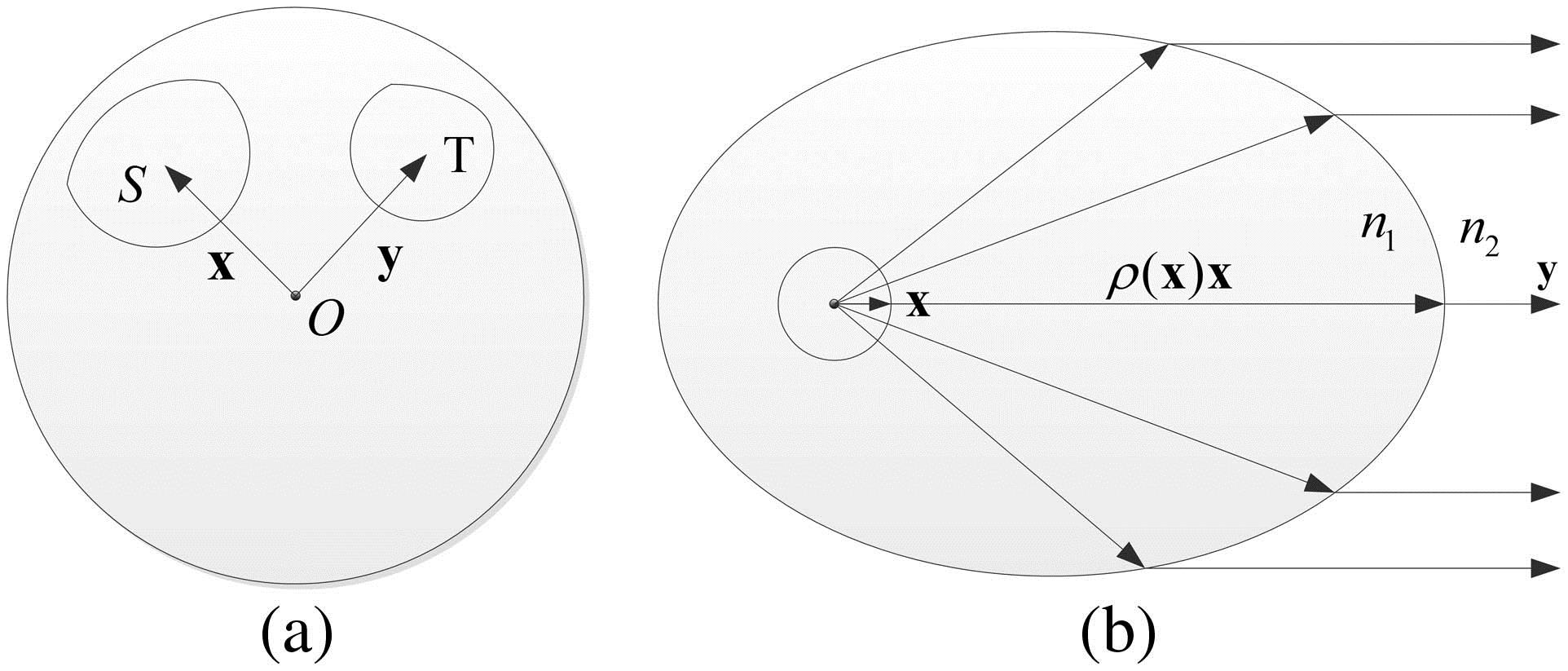
The problem of reshaping the light from an LED to a uniform distribution within a specified angle is similar to the reflector antenna design problem. As shown in Fig. 1(a), we assumed that the LED is a point light source placed at the origin, with a light intensity in the -direction. Suppose the light ray in the -direction is refracted by the outer surface of the reshaping lens in the -direction with a light intensity . The direction Vectors and belong to Sets and , respectively. The existence, uniqueness, and regularity of the weak solution of the reflector problem have been studied[4,5]. Based on the construction of the weak solution, a numerical method called supporting paraboloids was developed[6]. Furthermore, a linear programming algorithm was proposed[7,8] which was solved as a variational problem within the framework of the Monge–Kantorovich mass-transfer problem. Recently, a faster and direct calculation algorithm was developed, which combined these two methods[9,10]. A target flux estimate method was also developed[11] by using the intersection property of conics to accelerate the speed of the supporting paraboloids algorithm.
Figure 1.(a) Problem of reshaping the light of LED is about to map the Vector of Set to the Vector of the Set ; (b) refracting property of ellipsoid. As long as the incident angle is smaller than the critical angle, the light from the focus will be refracted by the upper part of the ellipsoid parallel to its major axis.
In this Letter, we propose an optical system consisting of five lenses. Each of the lenses transform the LED’s light to a uniform distribution in a hemisphere. We use the supporting paraboloids method to calculate the shape of the lenses. Figure 1(b) schematically shows an ellipsoid surface refracting light from the origin to render it parallel to the major axis; the surface separates Medium 1 of refractive index from Medium 2 of refractive index . Assume that light in the -direction is refracted at the point to direction . According to Snell’s law, the polar radius of the surface can be calculated as where , and is a constant. In our design context, Medium 1 is optically denser than Medium 2, which implies that . As the surface in Fig. 1(b) is ellipsoid, the constant is called the focal parameter, which can control the size of the ellipsoid.
Sign up for Chinese Optics Letters TOC. Get the latest issue of Chinese Optics Letters delivered right to you!Sign up now
For calculating the lens surface using the supporting paraboloids method, we discretize the target Set into finite points and the corresponding light intensity is . This light intensity value satisfies the energy conservation law
Assuming the lens is constructed by a finite number of ellipsoids each of the ellipsoids refracts the light from the LED to one of the directions . For each incident light ray in the -direction, the ellipsoid with the maximum polar radius would refract this incident light to the ellipsoid’s corresponding direction. By changing the focal parameter of each ellipsoid, we can obtain the light intensity in every direction of the target set. To control the size of the lens during this calculation process, the constant was kept unchanged in one of the ellipsoids called the “reference ellipsoid”. We have set the reference ellipsoid as and its focal parameter as . In order to ensure that all of the LED light is refracted by the reference ellipsoid, the initial focal parameter of other ellipsoids must satisfy The flowchart of the algorithm is shown in Fig. 2.
Figure 2.Flowchart of computing the construction ellipsoids of the lens.
After the computing is completed, we can construct the lens using this ellipsoid. Since the number of the ellipsoids is finite, the lens is built up by a faceted surface. However, the manufacturing at the edge between different patches would have more error. The classical numerical integration method[12] can be used to obtain a continuous surface. However, this method has an inherent error because the predefined source-target map may not be the actual map between the source and target sets. The lens constructed with the ellipsoids is the weak solution of the reshaping problem. By using this weak solution, we can generate the actual source-target map. The lens computed by this map can be continuous without any inherent error.
Figure 3 shows a 3D model of the reshaping lens and transmitter. The lens is generated by 50 ellipsoids. The input surface of the lens is semi-spherical at the bottom to accommodate the LED chip and to prevent changes in the direction of the light. The transmitter has five lenses, and the LED chips are arranged in a star shape. In this system, we use the Cree XP-E as the light source which has a light emitting area of . Figure 4 shows the simulation result of the light intensity using the optical design software Tracepro. The uniformity of the light intensity reshaped by this lens is 0.91, and the optical efficiency is 91.39%. In contrast, the original LID of the LED is far from uniform, and the light attenuates rapidly when the view angle is larger than 45°. Figure 4 also that the lens has 0.90 uniformity and 90.78% optical efficiency when simulated with the actual model of Cree XP-E.
Figure 3.3D model of the reshaping lens and transmitter.
The effect of the installation error was also investigated to include displacement in the –plane () and axis (). Figure 5(a) shows that when the distance between the lens center and LED chip center increases from 0 to 1 mm, the uniformity decreases from 0.91 to 0.50, whereas the optical efficiency exhibits almost no change. The relationship between the uniformity and the distance between the LED chip plane and the bottom plane of the lens is shown in Fig. 5(b). Here, when changes from to 0 and then to 1 mm, the uniformity changes from 0.32 to 0.91 and then to 0.39, respectively. It is evident that has more of an impact on the uniformity than . On the other hand, the optical efficiency has almost no affect when changes.
Figure 5.Effect of installation error; (a) displacement in –plane; (b) displacement in axis.
Figure 6 shows the relative LID when five optical elements are combined as an array. As shown, when the view angle is larger than 80°, the light intensity of the array drops as compared to the single element. This drop in light intensity is due to the short distance between the center lens and the edge lens, causing the light to be blocked by the other lenses. Although increasing the distance between the LEDs would potentially solve this problem, this level of uniformity is acceptable for meeting our design goal. The priority of this system is compactness.
Figure 6.Relative intensity of single optical element and five elements combination.
Figure 7 shows the fabricated lens installed with an LED. We have measured the light intensity of the system to verify the design. As shown in Fig. 8, the fabricated lens has 0.88 uniformity which coincides with the simulation results.
Figure 7.Fabricated lens and the optical system installed in an aluminum plate with an LED.
In conclusion, we design an optical system for handheld underwater wireless optical communication to reduce the difficulties of targeting the receiver. We utilize the supporting paraboloids method and numerical integration method to compute the lens surface data. The simulation result with an actual LED model shows that the designed lens can achieve a light intensity uniformity of 0.90 and optical efficiency of 90.78% in the hemisphere space. After the lens is fabricated, the results of this work show that the optical system can achieve 0.88 uniformity LID in nearly semi-sphere space. We believe a transmitter with this optical system can easily target the receiver.
References
[1] R. Li, Y. Wang, C. Tang, Y. Wang, H. Shang, N. Chi. Chin. Opt. Lett., 11, 080605(2013).
[2] H. Dong, H. Zhang, K. Lang, B. Yu, M. Yao. Chin. Opt. Lett., 12, 052301(2014).
[3] E. F. Schubert, J. K. Kim. Science, 308, 1274(2005).
[4] L. A. Caffarelli, V. I. Oliker. Weak solutions of one inverse problem in geometric optics(1994).
[5] X. Wang. Inverse Problem, 12, 351(1996).
[6] L. A. Caffarelli, S. A. Kochengin, V. I. Oliker. Contemp. Math., 226, 13(1999).
[7] T. Glimm, V. Oliker. J. Math. Sci., 117, 4096(2003).
[8] X. Wang. Calc. Var., 20, 329(2004).
[9] C. Canavesi, W. J. Cassarly, J. P. Rolland. Opt. Lett., 37, 3852(2012).
[10] C. Canavesi, W. J. Cassarly, J. P. Rolland. Opt. Eng., 53, 31306(2014).
[11] C. Canavesi, W. J. Cassarly, J. P. Rolland. Opt. Lett., 38, 5012(2013).
[12] W. B. Elmer. The Optical Design of Reflectors(1980).