We propose and demonstrate a dual-channel microfluidic sensor based on a side-hole fiber (SHF) with two long-period fiber grating (LPFG) structures. There are two air holes in the SHF, which are natural microfluidic channels. We fabricate two LPFGs (long-period gratings LPG-A and LPG-B) in the SHF with the resonance wavelengths of 1268.7 nm and 1385.8 nm, respectively. Results show that the refractive index sensitivities of LPG-A and LPG-B are ?76.0 nm/RIU and ?71.1 nm/RIU, respectively. One can measure the refractive index of liquid samples in two channels simultaneously. The proposed dual-channel microfluidic sensor has advantages of good linearity response, fluidic technology compatibility, and easy light input/output coupling and system integration, which helps the sensor to have a potential application in environmental detection and food safety detection.
A holey fiber contains air holes along its axial direction, like a microstructure fiber (MSF)[1,2] and a photonic crystal fiber (PCF)[3,4], and MSFs include a hollow eccentric fiber (HEF)[5,6] and a side-hole fiber (SHF)[7]. A holey fiber is suitable for chemical sensing or detection in situ with minimal sampling volume. Compact sensors based on holey fibers, also called microfluidic fiber sensors, have the advantages of being easy to combine with the communication system and integrate with a lab-on-a-chip system[8,9]. Air holes in the micrometer scale in the holey fiber are natural channels for liquid samples to pass through. After chemical or biological surface modification, the applications of those channels are greatly enhanced.
The long-period fiber grating (LPFG) structure with a period of typically hundreds of micrometers is known to couple the fundamental core mode to co-propagating cladding modes in both conventional optical fibers[10,11] and holey fibers[12,13], resulting in significant attenuation at some resonance wavelengths in the transmission spectrum. Since the wavelength and the power of the attenuation band of the LPFG are sensitive to the changes of external environments, LPFGs can be used as multi-parameter sensors for temperature, bending, strain, stress, and refractive index (RI)[14–16] measurements. Several microfluidic chemical/biological sensors based on holey fibers have been proposed, including the PCF sensor based on evanescent waves[17,18] or LPFGs[19,20] for bio-sensing, and the HEF/SHF sensor based on LPFGs[1,3] for RI measurement. However, the above sensing structures have some drawbacks. (1) Only one microfluidic channel is achieved in the structures mentioned above, the measurement efficiency is low. (2) For the PCF sensor based on LPFGs, which is written by a laser, one should control the laser energy density strictly to avoid air holes collapsing. (3) Typically, the air hole diameter of the PCF is about 2–4 μm[18,19,21]. The size of the microfluidic channel is too small to fill the liquid sample, and the sample injecting speed is low.
In this Letter, we propose and demonstrate a microfluidic sensor with two channels for RI measurement simultaneously based on the dual-LPFG structure in a SHF. The proposed dual-channel sensor can provide RI simultaneous measurement of two samples in two channels. The size of the air hole in the fiber is large, and it is convenient for liquid samples flowing in/out.
Sign up for Chinese Optics Letters TOC. Get the latest issue of Chinese Optics Letters delivered right to you!Sign up now
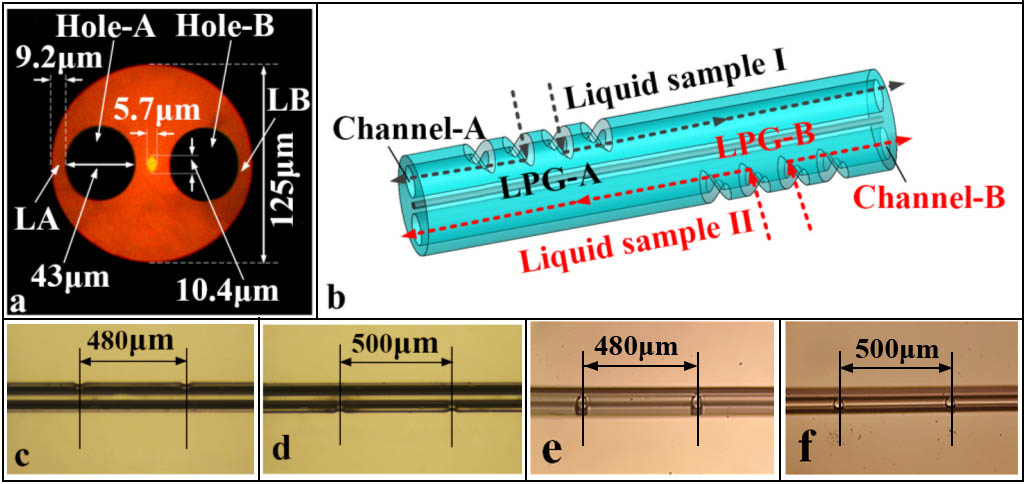
We employ an SHF with twin air holes in the fiber [see Fig. 1(a)] to fabricate the sensing probe. We name them Hole-A and Hole-B, respectively. The cladding diameter of the SHF is 125 μm, and the air hole diameter is 43 μm. The elliptical-doped silica core is in the center of the SHF, which has a short diameter of 5.7 μm and a long diameter of 10.4 μm. The thinnest part [see Zone LA and Zone LB in Fig. 1(a)] of the hole-cladding-air interface is 9.2 μm. We employ a high-frequency laser to carve Zone LA and Zone LB periodically to fabricate two LPFGs in the SHF. The air holes with a 43 μm diameter do not collapse during the long-period grating (LPG) fabrication and are suitable for microfluidic sensing. We name the LPFG in the side of Hole-A (Channel-A) to be LPG-A, and the LPFG in the side of Hole-B (Channel-B) to be LPG-B [see Figs. 1(b)–1(f)]. The resonance wavelength of LPG-A is 1268.7 nm with the energy attenuation of 16 dB, and the resonance wavelength of LPG-B is 1385.8 nm with the energy attenuation of 18 dB.
Figure 1.(a) Profile image of the SHF. (b) Schematic diagram of the dual-channel sensor based on dual LPFGs. (c) Side view of LPG-A. (d) Side view of LPG-B. (e) Top view of LPG-A. (f) Top view of LPG-B.
The LPFG is a periodical structure with the order of a fraction of a millimeter. The RI periodically varies along the axial direction of the fiber. The guided fundamental mode in the fiber is coupled with forward-propagating cladding modes when a phase-matching condition is satisfied. These modes decay rapidly as they propagate along the fiber axis due to absorption and scattering losses at the cladding-air interface. Significant attenuation at some resonance wavelengths will be observed in the transmission spectrum. The phase-matching condition for the LPFG is expressed as[13]where is the resonance wavelength of the cladding mode coupled by the fundamental core mode, and and are the effective RIs of the fundamental core mode and the cladding mode, respectively. The strong dependence of on makes the LPFG inscribed in the SHF be an RI transduction optofluidic platform that is highly sensitive to the changes in induced by any physical, chemical, or biological perturbations near the cladding structure.
The RI sensitivity of the dual-LPFG sensor is determined by the dependency of an effective index on the waveguide structure and phase-matching condition of the LPFG. Therefore, when we only inject one sample in Channel-A, the sensitivity of LPG-A is higher than the sensitivity of LPG-B. Similarly, when we only inject one sample in Channel-B, the sensitivity of LPG-B is higher than the sensitivity of LPG-A. In summary, there exist two sensitivities in each LPFG sensing channel. Assuming the proposed dual-channel sensor works within a linear range, the response of the sensor to the dual-channel RI can be expressed as where and are the wavelength shifts of LPG-A and LPG-B, respectively. and are the changes of liquid sample RI in Channel-A and Channel-B, respectively. The 2×2 coefficient matrix consists of four terms, namely, , , , and , where is the RI sensitivity of LPG-A when injecting the sample solution into Channel-A. is the RI sensitivity of LPG-B when injecting the sample solution into Channel-A. is the RI sensitivity of LPG-A when injecting the sample solution into Channel-B. is the RI sensitivity of LPG-B when injecting the sample solution into Channel-B.
When we do the measurement, firstly, we should experimentally analyze the independent response of each LPFG in different channels, obtaining the results of , , , and . Secondly, we should obtain the matrix equation with and and measure the RI of samples in dual channels simultaneously and directly.
We employ two tunable fixture holders to fix the SHF. We adjust the direction of SHF and ensure the Zone LA is in the effective zone of the laser (-H10, Han’s Laser) and write the LPG-A. Then, we rotate the holders by 180° to ensure that Zone LB is in the effective zone of the laser and write the LPG-B. The axial distance between LPG-A and LPG-B is several centimeters. The grating period of LPG-A is 480 μm, and the grating period of LPG-B is 500 μm. The grating length of LPG-A is 24 mm, and the grating length of LPG-B is 25 mm.
Figure 3 provides the transmission spectrum of dual LPFGs. After fabricating the first LPFG (LPG-A), we record the transmission spectrum, as shown in the black line in Fig. 3. The resonance wavelength of LPG-A is 1268.7 nm, and the energy attenuation of the dip is 16 dB. Then, we record the transmission spectrum of the sensor when two LPFGs are written. The red line in Fig. 3 shows the resonance wavelengths of LPG-A and LPG-B. The resonance wavelength of LPG-B is 1385.8 nm, and the energy attenuation of the dip is 18 dB. It is worth mentioning that we fabricate the LPFG by configuring periodic defects in the cladding instead of writing the LPFG in the fiber core; we do not observe birefringence-induced mode splitting in the LPFG spectrum as in some birefringent fibers[23,24]. Therefore, we obtain one dip (Dip-A) introduced by LPG-A and obtain another dip (Dip-B) introduced by LPG-B.
Figure 3.Transmission spectra for LPG-A (black line) and dual LPGs (LPG-A and LPG-B, red line) in air.
We configure the real-time investigation setup (see Fig. 4) to measure the RI of the liquid sample. We employ two glass capillaries to seal two LPFG regions. We inject a microtubule into one end of each glass capillary to launch the liquid sample.
Figure 4.Schematic diagram of the experimental setup.
Two single mode fibers (SMFs) are used to couple in and out of the laser power. We grind the tip of the SMF to be frustum shaped to flow out the liquid samples. The fiber grind angle is , and the μ. We employ two micro-pumps (LSP01-1A, Longer™) to inject the liquid samples into the sensing channels. We wash the sensing channels with distilled water for 10 min and then with air for 10 min before and after a sample test. The testing samples flow through channels constantly for 20 min to ensure accurate measurement.
The testing results are provided in Fig. 5. The liquid sample used in the experiment is glyceryl solution. When the RI in Channel-A ranges from 1.335 to 1.395 with the step of 0.01, the sensitivity of LPG-A is −76.0 nm/RIU, and the sensitivity of the LPG-B is −47.9 nm/RIU. Similarly, when the RI in Channel-B ranges from 1.335 to 1.395 with the step of 0.01, the sensitivity of LPG-A is −40.6 nm/RIU, and the sensitivity of LPG-B is −71.1 nm/RIU. Two resonance dips have different RI sensitivities. Therefore, Eq. (2) can be expressed as
Figure 5.(a) The transmission spectrum of LPG-A when we load the liquid samples in Channel-A. (b) The transmission spectrum of LPG-B when we load the liquid samples in Channel-A. (c) The transmission spectrum of LPG-A when we load the liquid samples in Channel-B. (d) The transmission spectrum of LPG-B when we load the liquid samples in Channel-B. (e) RI sensitivity of LPG-A and LPG-B when we load the liquid sample in Channel-A. (f) RI sensitivity of LPG-A and LPG-B when we load the liquid sample in Channel-B.
We may obtain an exact matrix equation with and as where . Therefore, we may obtain the matrix coefficients as
In addition, we perform the simultaneous measurement of RI in dual channels by using the proposed dual-channel sensor based on SHF. The performance of this simultaneous measurement configuration is experimentally determined by undertaking RI in Channel-A variations at a fixed RI in Channel-B and the other way around. The results are shown in Fig. 6. From these results, root mean square (RMS) resolutions of ±0.0021 RIU in Channel-A and ±0.0028 RIU in Channel-B are determined for RI measurements in dual channels, respectively.
Figure 6.Sensor output as determined by Eq. (5) for variation of RI in one channel at a constant RI in the other channel.
The deviation is mainly due to the following reasons. (1) The change of the ambient temperature will affect the RI of the glycerol solution, which will cause the deviation of the measured results. (2) The residual of the liquid samples introduced by the last measurement will also cause a deviation of the measurement results.
In conclusion, a simple and effective technique for simultaneous measurement of two microfluidic channels using two closely spaced fiber gratings embedded in one SHF is described. The experimental results of this type of grating device show that this LPFG sensor can increase the measurement rate and has an excellent performance in terms of linearity and sensitivity. This kind of microfluidic sensor based on SHF has the potential capability to work together in a lab-on-a-chip system.