Abstract
We propose a cross-talk-free integral imaging 3D display based on a pyramid pinhole array. The pyramid pinhole array is used to provide a point light source array. Since the generated point light source array is behind a transmission-type display panel that displays an elemental image array, the pseudoscopic problem can be resolved. By setting the appropriate parameters for the pyramid pinhole array, the cross talk can be eliminated. We experimentally verify the reconstruction of the orthoscopic and cross-talk-free 3D images using the proposed 3D display.1. INTRODUCTION
Among the variety of 3D displays, the integral imaging (II) 3D display proposed by Lippmann in 1908 [1] is considered one of the most promising technologies because of its many advantages, such as continuous viewing points, full parallax, full-color 3D images, no visual fatigue, and no need for any special viewing devices [2–6]. An II 3D display includes two processes including a pickup process and a display process. In the pickup process, a microlens array is used to capture different perspectives of a 3D object, and the 3D information of the object is spread into a 2D array called an elemental image array (EIA). Based on the reversibility of the optical path in the display process, another microlens array, which is the same as the one used in the pickup process, reconstructs a 3D image just like the original 3D object. A pinhole array can be used to replace the microlens array in the display process, because the pinhole array is free from linear distortion and has a virtually infinite depth of focus. However, cross talk and pseudoscopic problems are the two problems that hinder the practical application of II 3D displays. The cross talk is caused when the light emitted from each elemental image (EI) is partially transmitted by its corresponding pinhole and partially transmitted by the adjacent pinholes, and the flipped images are observed in the cross talk zone. The pseudoscopic problem results from the different inverse directions of the pickup and display processes. Many methods have been proposed to resolve these problems.
The pseudoscopic-to-orthoscopic (PO) conversion can be achieved by using a gradient-index microlens array [7] or two-step pickup method [8]. However, these methods need expensive optical elements or an additional pickup process, which induces degradation and loss of the light information. With the development of computational technology, a method that rotates each EI by 180° around its center has been proposed and has become the simplest method of PO conversion, and a smart pixel mapping method based on the virtual pickup of a reconstructed 3D image with a virtual pinhole array has also been proposed [9]. However, these methods are hard to perform in real time because of the computational load. A transformation matrix formalism enables the real-time PO conversion [10]; however, the transformation for a high-resolution EIA also wastes time. The cross talk can be eliminated by setting an optical barrier array between the microlens array and EIA [11]. Recently, our group has also proposed a few cross-talk-free II 3D display systems. One of them uses a double plano–convex microlens array by reflecting the cross talk lights [12], and another one uses a tilted barrier array consisting of orthogonally polarized sheets [13]. However, it’s hard to fabricate the optical barrier array, the double plano–convex microlens array, and the tilted barrier array. All of the above methods cannot resolve the pseudoscopic and cross talk problems at the same time.
In this paper, we propose a pyramid pinhole array (PPA)-based II 3D display in which the pseudoscopic problem is automatically resolved without any image processing and the cross talk is also eliminated simultaneously.
Sign up for Photonics Research TOC. Get the latest issue of Photonics Research delivered right to you!Sign up now
2. STRUCTURE AND PRINCIPLE
The schematic diagram of the proposed 3D display is shown in Fig. 1(a). The PPA is formed by a set of pyramids with a pinhole on the top of each pyramid, as shown in Fig. 1(b), and the bottom of each pyramid is attached to a transparent glass substrate. A backlight unit (BLU) is used to provide the white light through the PPA. The side walls of the PPA block the light, and only the pinhole on the top of each pyramid can transmit the light. So the combination of BLU and PPA acts as a point light source array (PLSA). A transmission-type display panel, for example, a liquid-crystal display (LCD) panel, is used to display an EIA. The PPA and the EIA are center-aligned, and their pitches are identical.
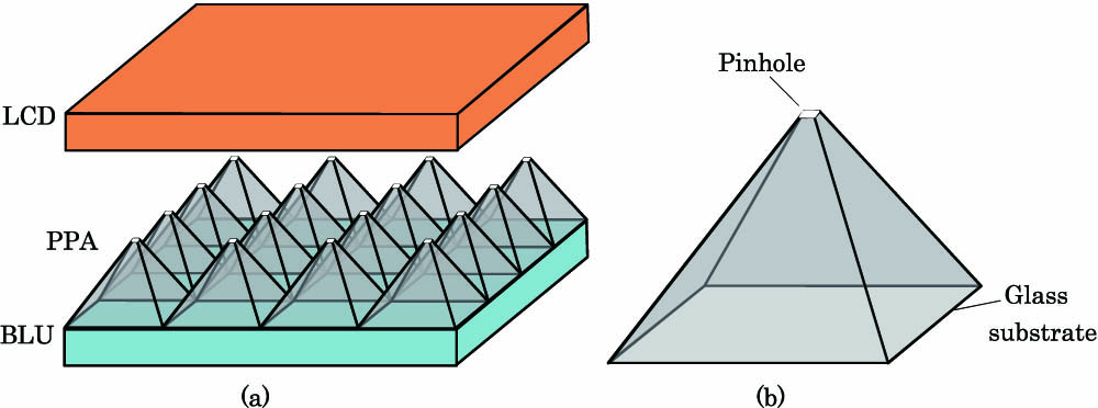
Figure 1.Schematics of (a) the proposed 3D display and (b) a pyramid with a pinhole.
Figure 2 shows the principle of the proposed II 3D display. The BLU and PPA are simplified to a PLSA behind the LCD panel, as shown in Fig. 2(b). The lights from the PLSA illuminate the EIA displayed on the LCD panel, the reverse extension lines of the lights reconstruct a virtual 3D image, and the observer sees the pixel that lies on the straight lines linking the point light sources and the observer. For the EIA directly obtained by a microlens array in Fig. 2(a), an orthoscopic virtual 3D image is integrated at the intersection point by the extension of the lights emitted from the same homologous pixels, as shown in Fig. 2(b). The 3D images reconstructed by the proposed 3D display are equivalent to the one that is reconstructed by the conventional 3D display when each EI is rotated by 180° around the center. So in the proposed 3D display, the reconstructed 3D image is orthoscopic, and the PO conversion is not needed.

Figure 2.Principle of (a) the pickup process and (b) the proposed display process.
Figure 3 shows the principle of the cross-talk-free II 3D display using the proposed 3D display. The divergence angle of the lights transmitted from the pinholes of the PPA can be expressed as where is the pitch of the PPA and also the pitch of the EIA and is the height of the PPA. The distance between the pinholes of the PPA and the LCD panel is . When , part of each EI cannot be illuminated by the lights, and it will result in incomplete 3D images. We call the part of the EI that is not illuminated the dead zone, shown by the dark gray areas in Fig. 3. When , the light from the pinhole of each pyramid can illuminate part of its adjacent EIs, and this will also cause cross talk images. We call the part of the EI that is illuminated by the lights from at least two pinholes the cross talk zone, shown by the red areas in Fig. 3. Only when is each EI exactly illuminated by the light from its corresponding pinhole. So, by setting , the lights transmitted from the pinholes on the top of the PPA can only illuminate their corresponding EI, and the cross talk between adjacent EIs is eliminated.
Figure 3.Principle of the proposed cross-talk-free II 3D display.
Based on the above theoretical analysis, the 3D image reconstructed by the proposed II 3D display can be free from pseudoscopic and cross talk problems.
3. EXPERIMENTS AND RESULTS
In the experiments, we develop two prototypes for the proposed and conventional 3D displays, and the pinhole array is placed in front of the display panel in the conventional prototype. In the proposed prototype, the handmade pyramids are made of a polyethylene film, and all the pyramids are closely arranged in an array to form the PPA, as shown in Fig. 4. In both prototypes, a film is used to replace the LCD panel. The specifications of the two prototypes are shown in Table 1. Both prototypes have the same pitch, pinhole size, and resolution of EIs. And in the proposed prototype, the distance between the pinholes of the PPA and the LCD panel is equal to the height of the PPA to avoid the cross talk.
Figure 4.Handmade PPA.
| | Proposed Prototype | Conventional Prototype |
|---|
| Array | 20×20 | 20×20 |
| Pyramid/pinhole pitch | 10 mm | 10 mm |
| EIA pitch | 10 mm | 10 mm |
| Pinhole size | 1 mm | 1 mm |
| Resolution of EI | 30×30 pixels | 30×30 pixels |
| Distance between | | |
| pinhole and EIA | 10 mm | 10 mm |
| PPA height | 10 mm | No |
Table 1. Specifications of the Two Prototypes
A 3D scene including the two letters “S” and “C” is picked up by a microlens array directly. The microlens array is composed of microlenses whose lens pitch is 10 mm and focal length is 10 mm. The letters “S” and “C” are 10 and 45 mm away from the microlens array, respectively, which means that “S” is in front of “C”. The reconstruction experiments are performed, and the EIA that is directly obtained by the microlens array is displayed in the two prototypes. Figure 5 shows the schematic diagram of the experimental setup.
Figure 5.Schematic diagram of the experimental setup.
Figure 6 shows the different views of the 3D images reconstructed by the proposed prototype. No cross talk is observed, though the handcrafted PPA is not uniform and perfect. The movment direction of the 3D images is the same as that of viewing point, which means that the reconstructed 3D images are behind the display screen. Meanwhile, “C” moves faster than “S”, which means that “C” has a greater depth. So, the reconstructed “S” and “C” are both virtual 3D images, and “C” is behind “S”, which is the same as in the original 3D scene. The experimental result shows that the proposed II 3D display can reconstruct cross-talk-free and orthoscopic virtual 3D images.
Figure 6.Different views of the 3D image reconstructed by the proposed prototype: (a) , (b) 0°, and (c) 20°.
Figure 7 shows the different views of the 3D images reconstructed by the conventional prototype. The cross talk is very obvious in both the left and right views. The movement direction of the 3D images is opposite to that of the viewing point, which means that the reconstructed 3D images are in front of the display screen. “C” moves faster than “S”, which means that “C” has a greater depth. So, the reconstructed “S” and “C” are both real 3D images, and “C” is in front of “S”, which means their depths are reversed. The experimental results show that the conventional II 3D display reconstructs the pseudoscopic real 3D images with cross talk.
Figure 7.Different views of the 3D image reconstructed by the conventional prototype: (a) , (b) 0°, and (c) 20°.
4. CONCLUSION
In conclusion, we propose an II 3D display using PPA to eliminate the cross talk and resolve the pseudoscopic problem simultaneously. In the proposed 3D display, the PPA is located behind the LCD panel to form a PLSA, which makes the reconstructed 3D image equivalent to the one that is reconstructed by the conventional II 3D display when each EI is rotated 180° around the center. The divergence angle of the light transmitted from each pinhole is fixed to illuminate only the corresponding EI, and the cross talk is eliminated completely. The experimental results show that in the proposed prototype, no cross talk is observed and the orthoscopic virtual 3D image is reconstructed by displaying the EIA picked up by the microlens array directly. If a computer-generated EIA is displayed using our proposed II 3D display, it is possible to reconstruct the orthoscopic real and virtual 3D images simultaneously. When a LCD screen is used, a finer and more colorful 3D effect can be obtained, since the pixel pitch of a LCD screen is smaller.
References
[1] G. Lippmann. La photographie integrale. C. R. Acad. Sci., 146, 446-451(1908).
[2] X. Xiao, B. Javidi, M. Martinez-Corral, A. Stern. Advances in three-dimensional integral imaging: sensing, display, and applications. Appl. Opt., 52, 546-560(2013).
[3] L. Zhang, Y. Yang, X. Zhao, Z. Fang, X. Yuan. Enhancement of depth-of-field in a direct projection-type integral imaging system by a negative lens array. Opt. Express, 20, 26021-26026(2012).
[4] X. Wang, H. Hua. Theoretical analysis for integral imaging performance based on micro scanning of a microlens array. Opt. Lett., 33, 449-451(2008).
[5] F. Jin, J. S. Jang, B. Javidi. Effect of device resolution on three-dimensional integral imaging. Opt. Lett., 29, 1345-1347(2004).
[6] J. Y. Son, S. H. Kim, D. S. Kim, B. Javidi, K. D. Kwack. Image-forming principle of integral photography. J. Disp. Technol., 4, 324-331(2008).
[7] J. Arai, F. Okano, H. Hoshino, I. Yuyama. Gradient-index lens-array method based on real-time integral photography for three-dimensional images. Appl. Opt., 37, 2034-2045(1998).
[8] H. E. Ives. Optical properties of a Lippmann lenticulated sheet. J. Opt. Soc. Am., 21, 171-176(1931).
[9] H. Navarro, R. Martínez-Cuenca, G. Saavedra, M. Martínez-Corral, B. Javidi. 3D integral imaging display by smart pseudoscopic-to-orthoscopic conversion (SPOC). Opt. Express, 18, 25573-25583(2010).
[10] J. Hyun, J. Kim, B. Lee. Solution of pseudoscopic problem in integral imaging for real-time processing. Opt. Lett., 38, 76-78(2013).
[11] H. Choi, S. W. Min, S. Jung, J. H. Park, B. Lee. Multiple-viewing-zone integral imaging using a dynamic barrier array for three-dimensional displays. Opt. Express, 11, 927-932(2003).
[12] Y. Wang, Q. Wang, D. Li, H. Deng, C. Luo. Crosstalk-free integral imaging based on double plano-convex micro-lens array. Chin. Opt. Lett., 11, 061101(2013).
[13] S. Tang, Y. Z. Wang, H. Deng, C. C. Ji, Q. H. Wang. Double-viewing-zone integral imaging 3D display without crosstalk based on a tilted barrier array. J. Soc. Inf. Disp., 21, 198-202(2013).


