The tunable multiple plasmon-induced transparency (PIT) effect is investigated numerically in a metal-insulator-metal (MIM) waveguide with three side-coupled rectangular resonators. The system exhibits dual-mode PIT effects in the visible and near-infrared regions. By adjusting the geometrical parameters of the structure, we can manipulate not only each single PIT window, but also the double PIT windows simultaneously. Our structures may have potential applications for optical communication, integrated optics, and optical information processing. The finite element method (FEM) illustrates our theoretical design.
Surface plasmon polaritons (SPPs) are the type of transverse electromagnetic waves coherently coupled to electron oscillation, propagating along the interface between metals and dielectric materials, with evanescently decaying fields on both sides[1,2]. SPPs have the most promising applications in highly integrated optical circuits and devices[3,4] for overcoming the diffraction limitation of light and manipulating light at the subwavelength scales. Optical elements based on SPPs have been simulated numerically and demonstrated experimentally[5–16]. Among many types of those optical elements, metal-insulator-metal (MIM) structures are widely used for not only supporting modes with deep subwavelength scales and high group velocity over a very wide range of frequencies but also for offering a very high optical confinement and acceptable propagation length, such as optical filters[5–7], optical switches[8], demultiplexers[9,10], sensors[11,12], and all-optical triplexers[13].
Electromagnetically induced transparency (EIT), a quantum destructive interference phenomenon, decreases the light absorption over a narrow spectral region in a coherently driven atomic system[17,18]. Since the sharp resonance and steep dispersion could achieve in EIT, this phenomenon has many prominent potential applications in slow light, biosensors, and optical storage[19]. Recently it has been demonstrated that an EIT-like spectrum can be realized in classical configurations. Plasmon-induced transparency (PIT) is the novel phenomenon analogous to EIT, which has the advantages of room-temperature manipulability, large bandwidth, and the merging of integrated with nanoplasmonic circuits[20,21]. In recent years, the PIT observed in coupled optical resonator systems was theoretically predicted and experimentally demonstrated in research[22–25].
In this Letter, a new PIT system that realizes obvious double transparency windows is proposed. It is numerically investigated and is composed of a MIM bus waveguide coupled to three rectangle resonators. By adjusting the geometrical parameters of the model we could manipulate not only each single PIT window, respectively, but also the double PIT windows simultaneously, and induce an off-to-on PIT optical response. Numerical simulations performed by the commercial finite element method (FEM) software COMSOL Multiphysics demonstrate our theoretical analysis.
Sign up for Chinese Optics Letters TOC. Get the latest issue of Chinese Optics Letters delivered right to you!Sign up now
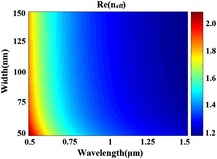
The dispersion relation of the fundamental plasmonic mode in the MIM waveguide is given by[26]where and are the dielectric constants of silver and air, respectively, and is the wave vector of light in vacuum. The can be calculated by Eq. (1). The real part of as a function of and is shown in Fig. 1. When is determined, Re will change little with the increase of the incident wavelength .
Silver, for its low absorption, is chosen in the MIM plasmon whose equivalent permittivity is given by the well-known Drude model[23]where is the dielectric constant at the infinite frequency, is the electron collision frequency, is the bulk plasma frequency, and stands for the angular frequency of the incident electromagnetic radiation.
Because the structure is invariant in the direction, we performed the simulation in a two-dimensional (2D) structure. The 2D plasmonic waveguide system investigated is illustrated schematically in Fig. 2, and the width of the slit is chosen as 50 nm (throughout this Letter). The plasmonic structure is composed of the MIM waveguide with three side-coupled rectangle resonators. Port 1 and Port 2 are input and output ports, respectively. The insulators in the white areas are assumed as air and its refractive index is 1 . Here, we marked the resonators as cavity I, cavity II, and cavity III, respectively. The lengths of the three side-coupled rectangle resonators introduced in the MIM plasmonic waveguide are set as ; represents the position shift of the upper two rectangles at the axis; the heights of the resonators are set as ; is the coupling separation between the bus waveguide and the cavity I (II); is the separation between cavity I and the cavity III. The metal in the purple areas is selected to be silver.
Figure 1.Real part of the effective refractive index versus the incident wavelength and the slit width in the MIM waveguide.
To analyze the influence of parameters on the transmission spectrum, research on the double same resonators (cavity I and cavity II) system is formed as the basis for later discussions. The simulation based on COMSOL software is carried out. In Fig. 2, the geometrical parameters of the structure without cavity III are set as follows: , , and . Figure 3(a) shows the transmission spectrum in the wavelength range of 600–1500 nm, and there are two dips at and 1334 nm, corresponding respectively to the 1st and 2nd modes. Figures 3(b) and 3(c) show the magnetic intensity distributions for Fano resonance dips at and 1334 nm, respectively, denoted by the red arrows. From Figs. 3(b) and 3(c), we could see that most of the energy would be coupled into the two side-coupled resonators and reflected back and forth. Namely, little energy would be transmitted, so the model can serve as a band-stop filter. However, when we put the same cavity III into the system and let and , the double PIT peaks appear for each mode as Figs. 4(f) and 4(l).
Figure 3.(a) Transmission spectrum of the MIM waveguide with two of the same side-coupled resonators; the contour profiles of the magnetic intensity distributions of the device at (b) and (c) .
Figure 4.(a)–(f) Off-to-on (left peak) transmission spectra of a three rectangle resonator PIT system with different values. (g)–(l) Off-to-on (right peak) transmission spectra of a three rectangle resonator PIT system with different values.
First, in order to realize the tunable PIT phenomena in the next section, we fixed the parameters of cavity II and cavity III, and explored the influence of the length of cavity I on the transmission spectrum. The other parameters are set as above. As can be seen from Figs. 4(a)–4(f), the mutative constructive parameters are set as , 540, 530, 520, 510, and 500 nm, respectively. With the length decreasing, one transmission peak increases to two peaks, namely the dual-mode PIT windows present and become increasingly apparent on account of the destructive interference between cavity I and the other two cavities. The peaks of the PIT transmission all present the blueshift effect and the left transparency window shows a progressively off-to-on optical response, with the cavity I being shorter. The -factor of the PIT window is defined as , where and are the transparency-peak wavelength and the full width at half maximum (FWHM) of the transparency window, respectively. As shown in Figs. 4(a)–4(f), the value of the right-side peak decreases (, , , , , and , at the 1st mode) dramatically but its transmittance increases gradually with a growing value, which demonstrates that the value of the right-side PIT window is more sensitive to the length of cavity I. This important feature can be employed to modulate the of the PIT resonance. The magnetic intensity distributions corresponding to the transparency windows for the 1st mode are visually illustrated in Fig. 5 when . From Fig. 5, when the incident light , most of the energy is stored in the rectangle cavity I and cavity III and is reflected, which results in a dip appearing in the transmission spectrum; similarly, when , most of the energy is stored in rectangle cavity I and cavity III, but the reflected energy is less than when ; when , most of the energy would only be coupled into cavity II, which is the same as in Fig. 3(c), but little energy into cavity I. However, while at , part of energy would be coupled into rectangle cavity II and cavity III, and SPPs can pass through the waveguide to the output port; when , part of the energy would be coupled into the three rectangle cavities, and SPPs can also pass through the waveguide to the output port. Therefore, both cases serve as the PIT “on” state.
Figure 5.Transmission spectrum of the MIM waveguide with three rectangle resonators when ; the contour profiles of magnetic intensity distributions of the device are at (a) , (b) , (c) , (d) , and (e) .
Second, similarly, only when the length of cavity II is changed, we can get the transmission spectrum exactly as Figs. 4(g)–4(l). With the length decreases from 525 to 500 nm and the interval is 5 nm, the right peak appears, namely, the dual-mode PIT windows present. An obvious off-to-on PIT response can be observed, and two peaks of the PIT transmission for each mode all exhibit a blueshift, with cavity II being shorter. Consequently, we could control the left (right) PIT window by adjusting the length of the side-coupled cavity I (II). Successively, for being flexible, the proposed PIT structure can be easily extended to the system with dual-mode PIT windows from off to on simultaneously by adjusting the position of the cavity III along the axis. Figure 6(a) shows a series of transmission spectra of the adjusted parameter . are set as 150, 100, 50, and 0 nm, and the other parameters remain unchanged. When varies from 525 to 500 nm, the transparency windows show progressively an off-to-on optical response simultaneously and the left peak presents the blueshift effect, then the right peak redshift, respectively. The corresponding magnetic intensity distributions at the three dips and two peaks for the 1st mode are displayed in Fig. 7 when . Comparing Figs. 7(a) and 5(a), Figs. 7(b) and 5(b), Figs. 7(c) and 5(c), Figs. 7(d) and 5(d), and Figs. 7(e) and 5(e), respectively, we found that they have almost the same field distributions, so we did not analyze them one by one here. However, it is worth mentioning that while cavity III does not couple with the other two cavities, and the transmission spectrum is the same as Fig. 3(a).
Figure 6.(a) Off-to-on transmission spectra of a three rectangle resonator PIT system with different values. (b) Off-to-on transmission spectra of three rectangle resonators PIT system with different values.
Figure 7.Transmission spectrum of the MIM waveguide with three rectangle resonators when ; the contour profiles of the magnetic intensity distributions of the device are at (a) , (b) , (c) , (d) , and (e) .
Last, similar simulations are conducted to investigate the influence of the separation between cavity I and cavity III on the transmission spectrum. Figure 6(b) shows a series of transmission spectra of the adjusted structure. The separations are set as 70, 60, 50, 40, and 30 nm, and the other parameters remain unchanged. With from 70 to 30 nm, compared with Fig. 6(a), the light propagation feature is almost the same, and the phenomenon is similar. When , cavity III does not couple with the other two cavities.
In conclusion, a model to achieve obvious double transparency peaks is proposed and demonstrated by COMSOL simulation. By changing the length of side-coupled cavity I (II), we can control the left (right) PIT window from off to on. Similarly, by adjusting the position of cavity III along the axis or the separation between cavity I and cavity III, we can manipulate the dual-mode PIT windows from off to on simultaneously. Our structures may have potential applications for optical communication, integrated optics, optical information processing, and so on.