Tiny but universal beam shifts occur when a polarized light beam is reflected upon a planar interface. Although the beam shifts of Gaussian beams have been measured by the weak measurement technique, the weak measurement for orbital angular momentum (OAM)-induced spatial shifts of vortex beams is still missing. Here, by elaborately choosing the preselection and postselection states, the tiny OAM-induced Goos–H nchen and Imbert–Fedorov shifts are amplified at an air–prism interface. The maximum shifts along directions both parallel and perpendicular to the incident plane are theoretically predicted and experimentally verified with optimal preselection and postselection states. These maximum shifts can be used to determine the OAM of vortex beams.
1. INTRODUCTION
Reflection and refraction at an interface between two different media are described by Snell’s law and the Fresnel formula [1–5]. For a bounded beam, however, Goos–Hänchen (GH) and Imbert–Fedorov (IF) shifts occur [6]. If the incident beam carries orbital angular momentum (OAM), the OAM affects the GH and IF shifts [6]. Additional OAM-dependent terms appear in both the GH and IF shifts [6–8]. The OAM-dependent beam shifts have attracted significant attention owing to the physical interest and their applications in the determination of OAM and manipulation of optical spin [6–10]. The giant optical spin splitting induced by OAM has been predicted recently when a higher-order Laguerre–Gaussian (LG) beam transmitted through an epsilon-near-zero metamaterial slab [10]. As was demonstrated recently, the GH and IF shifts of LG beams can be optimized by carefully designing the Fresnel reflection/refraction coefficients [11]. By modulating the Fresnel coefficients via graphene, the OAM-dependent GH and IF shifts can be well tuned [12,13].
Although methods have been proposed to enhance the GH and IF shifts, they are generally small, typically a few tenths of a wavelength [6]. A combination of a position-sensitive detector and a lock-in amplifier has to be employed to extract these tiny shifts [14]. In 2008, Hosten and Kwiat observed the spin Hall effect of light via weak measurement [15]. The spin-dependent shifts of the refracted beam from an air–prism interface were amplified and directly observed by a CCD camera [15]. The measurements of GH and IF shifts via this simple method were demonstrated by different groups through appropriately choosing the preselection and postselection states [16–20]. With the assistance of the weak measurement technique, the beam shifts have been widely used in precision metrology such as identifying the layer number of graphene and measuring thickness of Au film [21–23]. However, the weak-value amplifications for GH and IF shifts are limited within Gaussian beams. The weak measurement for OAM-induced GH and IF shifts of a vortex beam is still missing.
Here, weak-value amplification of the tiny OAM-induced shifts at an air–prism interface is demonstrated by carefully choosing the preselection and postselection states. The amplified beam shifts vary linearly with the incident OAM.
Sign up for Photonics Research TOC. Get the latest issue of Photonics Research delivered right to you!Sign up now
2. THEORY AND MODEL
A. Weak-Value Amplification Principle for OAM-Induced Shifts
The GH and IF shifts of vortex beams have been demonstrated by Merano et al.[8]. According to their work, for a vortex beam reflected from an air–prism interface, the GH shifts for horizontal () polarization (electric field parallel to the plane-of-incidence) and vertical () polarization (electric field perpendicular to the plane-of-incidence) are , while the IF shifts are , respectively. is the OAM of incident beam, , with being wavelength in vacuum. Parameters , with being the incident angle; further, and are the Fresnel reflection coefficients of and waves at the air–prism interface, and associates with conventional GH shift for an polarized Gaussian incident beam. The conventional IF shift is , where , [6]. One can conclude that the reflected vortex beam only undergoes IF shifts for incident polarization. It is worth pointing out that these OAM-induced shifts are smaller than a wavelength.
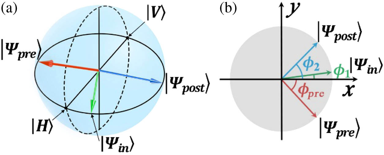
In order to amplify the small OAM-induced shifts, the weak value technique is employed. Here, both the GH (along the axis) and IF (along the axis) shifts are considered. Their quantum operators can be given by [18]respectively. The preselected polarization state of the system is prepared by reflecting the incident state on the prism [17]. As shown by Fig. 1(a), the incident polarization is , where , , with being linear polarization angle. Thus, the preselected state is . The Laguerre–Gaussian (LG) mode with OAM is employed as the point state of measuring device. It is initially prepared in state [24]. The amplitude distribution of LG point is , where is a normalizing constant, and is the waist of Gaussian function. The total initial state is then , whose evolution is dictated by the von Neumann Hamiltonian in two dimensions: [24,25]. A coupling constant is sufficiently small, and and are the momentum observables of the probe conjugate to two commuting position observables, and , respectively.
Figure 1.(a) Incident (green arrow), preselection (red arrow), and postselection (blue arrow) states of weak-value amplification represented in Poincare sphere. (b) Corresponding polarization angles.
After the weak interaction, we postselect the system in state by combining a quarter-wave plate (QWP) and a Glan linear polarizer (GLP2). The QWP makes a fixed angle of 45° to the horizontal axis, while the GLP2 makes an angle of . The point state then evolves into [24,25]According to Refs. [25,26], the spatial displacements of the point state in the plane can be calculated as where the weak values of GH and IF operators are , , respectively. and are the amplified GH and IF shifts, which both contain OAM-dependent and OAM-independent parts. These spatial shifts include not only the real part of the weak values but also the imaginary part except for because the LG point state is not factorable in the and dimensions.
In the weak-value amplification, the preselection and postselection states should be nearly orthogonal. We first prepare the preselection state in diagonal state . The required incident polarization state is , with the linear polarization angle being . This angle is denoted as in the following. When , the postselection state is , exactly orthogonal to the preselection state. By rotating the GLP2 a small angle from the orthogonal position, both the GH and IF shifts can be amplified (see Fig. 2). However, the amplified shifts mix the OAM-dependent and OAM-independent shifts for . Another scheme is proposed, where we keep the postselection state , and rotate the GLP1 a small angle from , namely, . The preselection state is then . The polarization angle of preselection state is , as shown by Fig. 1(b). From Eqs. (4) and (5), the weak-value amplified GH and IF shifts are where is the first derivative of , with respect to the incident angle . In the calculation, the coupling constant is set to be . From Eqs. (6) and (7), one finds that, with a small angle , the OAM-induced GH and IF shifts can be amplified simultaneously, while the OAM-independent shifts vanish. Therefore, by elaboratively designing the preselection and postselection states, we amplified exclusively the OAM-induced shifts. Although the preselection state changes during measurement, for each small angle , the postselection state is nearly orthogonal to the preselection state. The deviation of the postselection state from the orthogonal position varies with ; thus, the OAM-induced shifts can be tuned by .
Figure 2.GH and IF shifts of the reflected vortex beam as functions of polarization angles and . In the numerical calculation, , μ.
We have used a quantum mechanical description to analyze the weak-value amplification principle for the OAM-induced shifts in order to provide good physical insight. However, the above theory will be invalid when approaches zero. Therefore, in order to obtain a more precise analysis for the OAM-induced GH and IF shifts, we next describe them by using standard wave optics.
The incident light field after GLP1 is , where is the Fourier transformation of the LG modes . and are the and components of the wave vector, respectively. The incident light field is then reflected by an air–prism interface. According to Ref. [6], the angular spectra of reflected and incident fields are connected by a matrix. In the first-order approximation, the reflected light field can be given by [2,6]where . The reflected light field passes through a QWP with an angle of 45° to the horizontal axis and then is selected by GLP2. The light field becomes Now the amplified shift (the beam centroid) can be straightforwardly calculated by as respectively, where the energy of the light field after GLP2 is The weak-value amplified GH and IF shifts each contain three terms: one OAM-independent term and two OAM-dependent terms. Equations (10) and (11) will reduce, respectively, into Eqs. (6) and (7) when and . By tuning the angles of and simultaneously, the amplified GH and IF shifts can be maximized.
Figure 2 shows the amplified GH and IF shifts and as functions of the polarization angles of and for the OAM , respectively. One can find from Fig. 2 that both the GH and IF shifts can be amplified near point . When , the preselection state is in the diagonal state. Both the and have a positive peak and a negative peak for incident beams, with and without OAM. Without OAM (), the peak value for is up to 59.4 μm, while is only 19.1 μm. The shifts and change signs when crosses 45°, where both the and vanish.
For the incident beams carrying OAM (), the maximum values of and increase with . The maximum values of are much larger than those of .
Generally, both the OAM-dependent and OAM-independent terms contribute to the total shifts of vortex beams. Figure 3 compares these contributions when and . When varies, the OAM-induced GH and IF shifts change signs, while the OAM-independent shifts keep. As shown in Fig. 3(b), the OAM-independent IF shift is much smaller than the OAM-dependent IF shift.
Figure 3.Comparisons of the contributions of the OAM-dependent and OAM-independent terms in (a) GH and (b) IF shifts when , .
However, when , the OAM-independent terms will not contribute to the total beam shifts [see Eqs. (10) and (11)]; thus, the GH and IF shifts vanish along the line of for the case of , as shown in Figs. 2(a) and 2(d). Therefore, should be set for the amplification of OAM-induced GH and IF shifts, as discussed in Section 2.A.
C. Optimized Amplification of OAM-Induced Shifts
When , the amplified GH and IF shifts are given by Eqs. (6) and (7), from which one finds that both GH and IF shifts diverge when angle approaches zero. When considering Eqs. (10) and (11), however, the shifts have maximum values [27], as shown by Fig. 2.
Figures 4(a) and 4(b) show the maximum values of the amplified OAM-induced GH and IF shifts changing with the incident angle for . The maximum values of and are obtained by rotating the angle of GLP1 for each incident angle.
Figure 4.Maximum OAM-induced (a) GH and (b) IF shifts changing with the incident angle. (c) Polarization angle and (d) optimized angle changing with the incident angle.
The maximum and vary with the incident angle and increase with the OAM . The maximum is almost identical for , indicating that the large OAM-induced IF shift can always be obtained by optimizing the preselection state for an arbitrary incident angle of .
The optimal preselection states for the OAM-induced beam shifts are found numerically for incident angle ranging from 0° to 90°. The for GH and IF shifts are identical. Figure 4(c) shows the angle changing with the incident angle; further, varies as the Fresnel reflection coefficients change with . The optimal deviation angle is shown by Fig. 4(d), and increases with OAM .
3. EXPERIMENTAL SETUP
The experiment setup is shown in Fig. 5. A Gaussian beam from a He–Ne laser is illumined onto a vortex phase plate (VPP-m633, RPC Photonics, Inc.). The vortex phase plate containing several vortex apertures can create 1-order to 8-order vortex charges by moving its position. A circular aperture filters out scattering light. The generated vortex beam is shown in the inset in Fig. 5. The vortex beam is then focused onto a prism by a lens L1 with a focal length of 250 mm. Before the prism, a Glan polarizer GLP1 is inserted to select the incident polarization state. The reflected beam from the air–glass interface is postselected by a combination of a QWP and a polarizer GLP2. The QWP is fixed to 45° from the horizontal direction, while the GLP2 can be rotated flexibly. The combination of QWP and polarizer can flexibly design the postselection state and, thus, has been used for selective weak-value amplification of the GH and IF shifts of a Gaussian beam in partial reflection [28]. The lens L2 (focal length 25.4 mm), L3 (focal length 125 mm), and a CCD (pixel size μμ) form an image system with an amplification factor of 4.8 [29]. Therefore, the beam shifts at the air–glass interface are projected in the image plane of the CCD. All the experimental results of beam shifts below are shown in their real size and compared with the theoretical prediction.
Figure 5.Experiment setup for the measurement of OAM-induced shifts by weak technique. Insets show the intensity distributions of the generated vortex beam after aperture and the beam in the image plane of CCD with GH and IF shifts.
Before measurement, we first find the incident polarization angle , which results in the preselection state in diagonal state. To do this, we fix the GLP2 to be 45° and rotate the GLP1 to minimize the energy outputted from GLP2. The position corresponding to the minimum outputted energy is because the preselection and postselection states are orthogonal to each other.
4. RESULTS AND DISCUSSION
By fixing , the amplified GH and IF shifts of vortex beams changing with are measured. Figure 6 compares experimental (dots) and theoretical (lines) results when the incident angle is and the OAM is , 2, 4, 6. The experimental and theoretical results do not match perfectly, although their tendencies with are identical. This is because the incident beams are not in ideal shape. The vortex beams are generated experimentally by passing a Gaussian beam through a vortex phase plate. They are not perfect LG modes; the intensity fluctuates along circular rings, as shown in the inset in Fig. 5. However, the incident beam is assumed to be perfect LG modes in the theoretical calculation. The break lines in the vortex phase plate scatter light, which will enter CCD and affect the measurement of beam shifts because the vortex beams after postselected are weak.
Figure 6.Experimental (dots) and theoretical (lines) results of the amplified OAM-induced (a) GH and (b) IF shifts changing with the angle of GLP1 .
As shown by Fig. 6, at , the energy of the transmitted light field through GLP2 is weakest, namely, . At this angle, there are no beam shifts with vanishing and . Both the and have a positive peak and a negative peak for each (). The positive peak positions for both and are 180.20° (), 180.26° (), and 180.31° () for , 4, 6, respectively. The negative peak positions locate at 179.80° (), 179.74° (), and 179.69° (), respectively. Therefore, , , and are the optimal preselection states for , 4, and 6, respectively. At optimal preselection states, the GH and IF shifts are maximized. The maximized IF shifts are larger than GH shifts.
The amplified GH and IF shifts changing with the incident OAM are investigated by fixing . The intensity patterns of the transmitted beams from GLP2 for and 180.7° are shown in Fig. 7(a), where the theoretical and experimental results are compared for , 2, 4, 6, respectively. As shown by Fig. 7(a), the intensity patterns keep in a Gaussian beam for . For , and the patterns are in similar semilunar shapes, which are enlarged with the increase of . Therefore, the beam centroid moves. Figures 7(b) and 7(c) show the beam shifts along and axes, respectively. The theoretical and experimental GH shifts match well. The small mismatches of the theoretical and experimental IF shifts may result from the unideal vortex incident beam. Both the GH and IF shifts increase gradually with . Thus, the amplified GH and IF shifts can be used to measure the OAM. The weak measurement scheme should be precisely as discussed in Ref. [30], and the required elements (polarizer, QWP, and prism) are frequently used in optical labs.
Figure 7.(a) Comparisons of the experimental (first and third rows) and theoretical (second and fourth rows) intensity patterns of the transmitted beam from GLP2. The amplified OAM-induced (b) GH and (c) IF shifts changing with the incident OAM for and 180.7°.
Figure 8 shows the amplified GH and IF shifts of vortex beams changing with angles and when the incident angle and the OAM , 3, 5, respectively. The experimental and theoretical results match each other. The amplified shifts can be tuned by both and . The maximum shift is up to 121.2 μm obtained experimentally at and .
Figure 8.Experimental (dots) and theoretical (lines) results of the amplified OAM-induced (a), (c) GH and (b), (d) IF shifts changing with (a), (b) for and (c), (d) for .
In conclusion, the OAM-induced GH and IF shifts of vortex beams have been simultaneously amplified by the weak measurement technique. By properly choosing the preselection and postselection states, the OAM-induced GH and IF shifts can be maximized. Notably, the IF shifts can always be maximized for an arbitrary angle larger than 15°. The IF shift is up to 121.2 μm for , , and . The maximum shifts increase with the incident OAM gradually. We believe the proposed weak measurement scheme for a vortex beam has potential applications in identifying OAM and exploiting the joint weak values of single-particle operators.