Ziwen Pan, Chengfei Zhang, Chengfeng Xie, Yongqiu Zheng, Haotian Li, Jun Tang, Jun Liu. Resonator integrated optic gyro based on multilevel laser frequency lock-in technique[J]. Chinese Optics Letters, 2018, 16(4): 040601
Copy Citation Text
The resonator integrated optic gyros (RIOGs) based on the Sagnac effect have gained extensive attention in navigation and guidance systems due to their predominant advantages: high theoretical accuracy and simple integration. However, the problems of losing lock and low lock-in accuracy are the bottlenecks, which restrict the development of digital RIOGs. Therefore, a multilevel laser frequency lock-in technique has been proposed in this Letter to address these problems. The experimental results show that lock-in accuracy can be improved one order higher and without losing lock in a variable temperature environment. Then, a digital miniaturized RIOG prototype () has been produced, and long-term (1 h) bias stability of 26.6 deg/h is successfully demonstrated.
Resonator optic gyros (ROGs) have become an important content and a new development direction in navigation and guidance systems due to the advantages of no lock-in effects compared with ring laser gyros[1–3] and no need for kilometers of fiber rings compared with interferometric fiber optic gyros (IFOGs)[4–6]. The highly integrated device is a key component for ROGs. The optical waveguide resonator fabricated by planar semiconductor technology takes on some good features, such as high processing repeatability and high device integration capacity[7–10]. Thus, ROGs based on the optical waveguide resonator have great potential in the field of angular velocity sensing and have attracted significant attention in recent years.
According to their resonator medium, ROGs are classified into resonator fiber optic gyros (RFOGs) and resonator integrated optic gyros (RIOGs)[11]. Sanders et al. fabricated an RFOG using a silicon optical bench and achieved better than 0.1 deg/h bias stability[12]. Maleki et al. fabricated a heterogeneous RIOG based on a calcium fluoride () whispering gallery mode resonator with the diameter of 7 mm, which reached 3 deg/h bias stability[13]. The best bias stability of 0.004 deg/s was reported for a RIOG with a buried type silica waveguide ring resonator (WRR)[14].
In RIOGs, the changes of rotation rate are detected from resonant frequency differences between clockwise (CW) and counterclockwise (CCW) of light in the WRR[15]. However, resonant frequency is sensitive to temperature, which inevitably causes a drift of resonant frequency. Generally, a high accuracy servo loop is employed to lock the laser center frequency, which suppresses reciprocity noise caused by the changes of temperature. Therefore, the frequency locking servo loop with high accuracy and stability is very important.
Sign up for Chinese Optics Letters TOC. Get the latest issue of Chinese Optics Letters delivered right to you!Sign up now
Frequency locking servo loop stability is reflected in long-term tracking of the resonant frequency. When resonant frequency drift is not in tracking range of the laser, the frequency locking servo loop fails. For fiber ring resonators, the laser can be locked in the next resonant frequency when the resonance frequency drifts out of the tracking range, but which also causes a large reset pulse that affects the gyro output state. To solve the reset noise, Ma et al. proposed an automatic reset technique for RFOG[16]. However, when the free spectral range (FSR) of the WRR exceeds the laser tuning range, the resonant frequency may disappear in the tuning range of the laser; hence, automatic reset cannot be applied.
The high accuracy frequency locking servo loop can suppress reciprocity noise, which also directly affects RIOG performance. To improve lock-in accuracy, a method of high frequency Pound–Drever–Hall modulation was reported by Lu et al.[17], and it also can be improved by lifting laser control accuracy in a digital system. The laser control accuracy can only be optimized by sacrificing the tuning range. Therefore, there is a contradiction between lock-in accuracy and laser tuning range.
To solve the contradiction, we propose a multilevel laser frequency lock-in technique based on a semiconductor laser in order to digitalize RIOGs with a widened FSR. This proposed method is effective for solving the problem of losing lock and improving the lock-in accuracy.
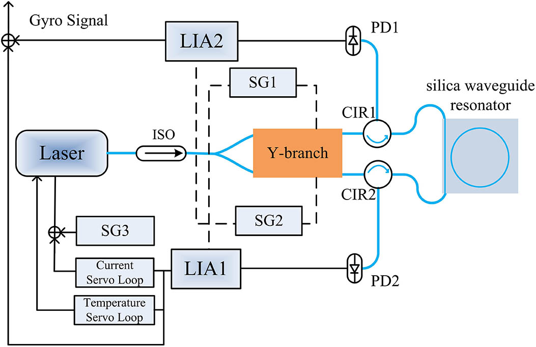
A schematic view of the digital RIOG system based on multilevel laser frequency lock-in is shown in Fig. 1. The linewidth of the semiconductor laser is very narrow (), and the center wavelength is 1550 nm. A proton exchanged lithium niobate Y-branch phase modulator is used to divide the lightwave equally and inject it into the WRR in CW and CCW directions. The signal generations (SG) generate modulation waves. The Y-branch arms are independent phase modulators, which are driven by different sinusoidal waveforms (SG1, SG2) with optimal amplitude and frequency[18–20].The WRR output lightwave is converted to a voltage signal by photodetectors (PD) and demodulated by the digital lock-in amplifier (LIA). Output from LIA1 is used as the error signal for the multilevel frequency lock-in servo loop, which includes a voltage control servo loop (VCSL) and temperature control servo loop (TCSL), and it locks the laser frequency to the CCW lightwave resonant frequency in the WRR. Before frequency lock-in, the SG3 generates a triangular wave signal for sweeping laser frequency. Output from LIA2 is used for the RIOG output RIOG after a closed loop. Signal generation, LIA, and data processing are completed in a field programmable gate array (FPGA) and integrated with the peripheral circuits, including the PD, 16 bit analog-to-digital (A/D) and digital-to-analog (D/A) chips, to form the digital system.
Figure 1.Schematic view of the digital RIOG system based on the multilevel laser frequency lock-in technique.
The multilevel laser frequency lock-in technique makes use of the semiconductor laser characteristics, where the center frequency can be tuned by adjusting the internal temperature and injection current. Ignoring the initial phase, the laser output field can be expressed as where is the amplitude, is the initial center frequency, is the VCSL feedback voltage, is the VCSL tuning coefficient, is the TCSL feedback signal, and is the TCSL tuning coefficient. In this system, is 25 MHz/V, maximum tuning range is , VCSL control accuracy is about 3.75 kHz using 16 bit LIA, is 20 GHz/°C, and we set the range at 20°C to ensure laser control accuracy better than 40 MHz. The TCSL control accuracy is low for the multilevel laser frequency lock-in technique, but its dynamic range is large. Therefore, TCSL should be the first order feedback. Before frequency lock-in, the range of scanning signal provided by SG3 is equal to the feedback range of the VCSL. To ensure the resonance spectrum into the VCSL, the range of the scanning signal is adjusted continuously by the TCSL. Second stage locking is performed by the VCSL when the resonant frequency is in the tuning range of the VCSL. To adjust the scanning range of the VCSL, the TCSL follows the changes of the VCSL feedback signal, while SG3 stops scanning.
The WRR with the finesse of 165.5 and resonant depth of 95% is fabricated by a polarization-maintaining waveguide. The ring length and diameter of the WRR are 18.8 and 6 cm, respectively. The power transmission for a silica WRR can be expressed as[21]where and are the input and output light fields, respectively, is the transmission coefficient of the coupling region, is the roundtrip factor, is the resonator roundtrip phase, is the resonator perimeter, and is the propagation constant.
The relation between the phase and the transmission is simulated by Eq. (2), as shown in Fig. 2. When the resonant frequency shifts from the black solid line to the blue dotted line due to environmental change, the VCSL’s tuning range would be tuned to the new resonant frequency by the TCSL. The VCSL tuning range is always covered in the resonant frequency. Hence, using this method, not only the problem of losing lock could be solved, but also reset noise due to resonant spectrum changes could be avoided. Using the multilevel laser frequency lock-in technique, the laser center frequency tracking range is determined by , which can accommodate large range drift of resonant frequency caused by environment changes, and VCSL laser control accuracy is determined by . The frequency lock-in accuracy can be further improved by reducing in the servo loop. Thus, the proposed method provides a large frequency tracking scale of the laser and enhances frequency locking accuracy.
Figure 2.Diagram of the proposed multilevel laser frequency lock-in technique.
In order to validate performance of the multilevel laser frequency lock-in technique, digital RIOG prototypes are also tested using a multilevel laser frequency lock-in servo loop and proportional integral VCSL over a range of controlled environmental temperatures. Starting from room temperature (27°C), the WRR was exposed to constantly increasing temperatures of 0.1°C over 30 s, where the gyro output and frequency lock-in stability were observed and compared. Alternately, ambient temperature was kept constant to ensure that the systems did not lose lock, and LIA1 outputs were observed to compare lock-in accuracy for different frequency lock-in servo loops.
The outputs of different frequency lock-in servo loops set to variable temperatures are shown in Fig. 3, respectively. Compared to the linear increases of environment temperatures from 27°C to 33°C in 1800 s, we clearly see that the gyro outputs show a change of periodic cliff with VCSL due to gyro system lose lock, but the output of the multilevel laser frequency lock-in technique is successive.
In order to investigate the reasons for VCSL cutting off periodically, the FSR can also be calculated as[22]where is the effective refractive index, is the light speed, and is the resonator perimeter length. The is larger than the laser tuning range in the VCSL. Rapid changes of temperature lead to the serious drift of the WRR resonant frequency. When the resonant frequency is out of the laser tuning range, the laser center frequency cannot reach the resonant frequency in the gyro system based on the VCSL, and then gyro output is cut off and feedback voltage jumps from the locked to the scan state, resulting in a large reset pulse. The resonant frequency of the next resonant mode will enter the tuning range of the laser with the further change of the temperature, and the gyro will get lock-in again. Figure 3. shows that the gyro output frequently loses lock with rapid changing of the temperature, approximately every 100 s, which means the system could not be used normally.
The resonant frequency drift rate is approximately 200–400 kHz/s at room temperature without external temperature control[23]. The semiconductor laser maximum tuning range is only 560 MHz, hence, practical applications in room temperature environments would experience approximately 1300 s of lost lock time, which is a fatal flaw. On the other hand, for the multilevel-control-servo-loop-based RIOG, the TCSL adjusts the VCSL tuning range before losing lock-in, and the VCSL voltage never reaches the cut-off due to the large range characteristics of temperature tuning. The voltage feedback tuning accuracy and speed are much higher than that of temperature feedback, hence, the TCSL ensures the continuous operation of the VCSL, and loses lock-in with a 6°C change over 1800 s. The tuning capability, which exceeds 400 GHz in the proposed system, has great adaptability to temperature change and greatly increases potential practical application prospects.
For validating the lock-in accuracy, the different frequency lock-in accuracies from LIA1 output over 1800 s using two schemes have been measured, as shown in Fig. 4. There are significant differences between only the VCSL and multilevel laser frequency lock-in techniques.
Figure 4.Frequency lock-in accuracy of different schemes.
There is evident long-term drift over 1800 s for the output of the VCSL because the resonant frequency drifts caused by temperature variation are smaller than control accuracy of the laser. The WRR resonant frequency could be easily changed by the external environment. The temperature coefficient for WRR based on silicon is about 1.33 GHz/°C, which means that WRR resonant frequency drifts approximately 13.3 MHz for 0.01°C change. Control accuracy for VCSL with output range and a 16 bit digital-to-analog converter (DAC) can achieve approximately 0.15 mV. The frequency control accuracy of the laser is about 3.75 kHz when the voltage tuning coefficient of the laser is 25 MHz/V. Thus, the frequency lock-in servo loop is unable to trace the noise in the condition where the drift is less than the control accuracy.
The tuning range is not necessarily considered for the multilevel laser frequency lock-in technique, so we can reduce the tuning coefficient or the tuning voltage range to improve control accuracy. In the experiment, control accuracy of 0.3 kHz was obtained by reducing VCSL gain. It pointed that output amplitude decreases significantly without drift. According to the Allan standard deviation, the lock-in accuracy improves from 10.22 to 0.92 deg/h using the multilevel laser frequency lock-in technique.
The proposed multilevel laser frequency lock-in technique was applied to a digital miniaturized RIOG prototype, and long-term (1 h) bias stability was assessed to be 26.6 deg/h, as shown in Fig. 5.
Figure 5.Digital miniaturized RIOG prototype (a) output at room temperature and (b) Allan deviation of typical 1 h test.
In summary, this Letter proposed a multilevel laser frequency lock-in method. This proposed method can be applied to extended FSR caused by decreasing resonator perimeter and ensure stable frequency lock-in across a wide temperature range. Experimental results indicate that the method solves the problem of losing lock-in in a temperature variable environment. Compared with the lock-in accuracy of RIOG without the multilevel laser frequency lock-in technique, the equivalent lock-in accuracy is increased more than 10 fold. Long-term bias stability of 26.6 deg/h over 3600 s at room temperature was obtained in an miniaturized digital RIOG prototype. The contradiction between the laser frequency tuning range and frequency lock-in accuracy is solved. This method has great practical and theoretical applications for digital gyroscopes.