Abstract
In this paper, we describe a new type of digital-to-analog converter (DAC) for optical wireless communication. Conversion occurs in the optical rather than the electrical domain. The overall intensity of the light transmitted by an array of light-emitting diodes (LEDs) is varied by changing the number of LEDs that are switched on. A number of different structures are described, and their compatibility with light dimming and overall energy efficiency are discussed. The linearity of the new DAC depends on the geometry of the system and on the variability in light output between individual LEDs.1. INTRODUCTION
As a result of their greater energy efficiency, white light-emitting diodes (LEDs) are rapidly replacing conventional fluorescent and incandescent lights. Although designed for lighting, unlike conventional forms of lighting, white LEDs can be modulated at frequencies up to 20 MHz [1], and as a result, they are forming the basis for a range of novel data communication and localization systems. A number of papers have described the use of these LEDs as transmitters in optical wireless communication (OWC) systems [2–6], demonstrating experimentally that very high data rates can be achieved. The use of LEDs for indoor localization is a very new idea, but one that is beginning to attract significant interest [7–10].
Most of the visible light communications (VLC) and localization applications require the LEDs to be driven with an analog signal, rather than simply be switched on or off [11]. To date, conventional electrical digital-to-analog converters (DACs) have been assumed, but these have some inherent incompatibilities with practical LED lighting systems.
Figure 1 shows a block diagram of a typical transmitter for VLC using a conventional electrical domain DAC. The signal values are calculated using some form of digital signal processing (DSP). The resulting digital value is converted to an analog electrical signal using a DAC, and this analog signal is used to drive the LED, or LEDs, that generate the light.
Sign up for Photonics Research TOC. Get the latest issue of Photonics Research delivered right to you!Sign up now
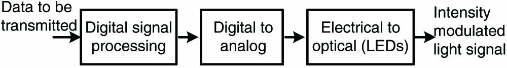
Figure 1.Block diagram of a conventional visible light transmitter using an electrical digital-to-analog converter (DAC).
LED nonlinearity is a problem when this simple configuration is used. Indoor optical wireless systems use intensity modulation and direct detection (IM/DD), so the signal is represented by the intensity of the light. Although the intensity of the light output from an LED is approximately proportional to the current driving it, even the residual nonlinearity of the LED can limit the overall performance of communication systems using these LEDs [12].
The simple configuration shown in Fig. 1 may also limit the overall energy efficiency of the system. Lighting is typically powered from an AC power source, but a DC source is required to drive the LEDs, so an overall energy efficient design must include consideration of the AC to DC conversion [13]. The relatively high-power analog signal required to drive the LEDs in this configuration is difficult to generate efficiently.
To provide sufficient light output, LED light fittings are typically constructed of multiple LEDs rather than a single LED [13]. The array of LEDs may be formed of a number of discrete LEDs [13], but increasingly manufacturers are producing devices with an array of LEDs within a single component [14].
This paper introduces a completely new type of DAC that takes advantage of these new LED array structures by using multiple LEDs to achieve digital-to-analog conversion in the optical rather than the electrical domain. (Experimental results showing successful application of this new technique to a system using orthogonal frequency division multiplexing are described in [15], which was published after the submission of this paper. That work was performed in parallel and completely independently of the work in this paper.) In the new DAC, a variable light output is produced by turning on, or off, a number of LEDs in the array rather than driving all of the LEDs with an analog signal. The intensity of the received light depends on the number of LEDs that are turned on. As each LED is either fully on, or fully off, the nonlinear characteristic of individual LEDs does not limit performance.
Note that the signals are combined in the optical domain, not in the electrical domain nor at the modulator. A similar problem arises in other optical applications when advanced modulation techniques are used, and over the years a range of multiple input configurations of Mach–Zehnder modulators have been proposed [16–18]. These are completely different from what is proposed in this paper. In high-speed optical fiber applications, another class of solutions to the problem of designing fast high-power DACs for optical applications is to jointly design the DAC and the amplification required for high powers, e.g., [19]. While this is addressing a similar problem, the solution is unrelated to the one we propose. Rather surprisingly, the most similar work that we are aware of is a DAC with electrical inputs and output, but in which the internal conversion is performed optically [20]. This technique was used to overcome the limitations of the all-electronic DACs available at that time (1989).
2. OPTICAL DOMAIN DIGITAL-TO-ANALOG CONVERTER
Figure 2 shows a simple example of the new transmitter structure. Digital-to-analog conversion is performed in the optical domain by an LED array. Figure 3 shows details of the LED array. The array consists of a number of LEDs, each of which can be separately switched on or off, under the control of the DSP. Assume, in the first instance, that the array consists of identical LEDs and that when switched on, each LED has the same current driving it. Then the light output from the LED array is proportional to the number of LEDs that are switched on.

Figure 2.Structure of transmitter using optical domain digital-to-analog conversion using an LED array.
Figure 3.Array of individually switchable LEDs.
This simple structure is analogous to the thermometer structure that can be used in electrical DACs [21]. A simple form of electronic DAC using a thermometer structure uses identical resistors in series. These form voltage divider circuits so that the voltages at the nodes between the resistors are the required analog voltages. Switches are connected between each node and the output, and the desired voltage is selected by closing the appropriate switch [22]. A total of switches is required.
In the new DAC, instead of switches connecting voltages, the switches switch on LEDs to construct an -bit DAC; LEDs and switches are required. The mapping of bits to LEDs must also be designed with care to avoid the nonuniform lighting effects that will occur if some LEDs are switched on for a greater percentage of the time than others. A similar problem has been described and solutions proposed in a light-dimming system using LED arrays [23].
In practice, LED luminaires are usually connected as strings of LEDs in series, rather than as a parallel array of LEDs, as this is more energy efficient [13]. In this case the array structure must be modified to that shown in Fig. 4. Then, the number of LEDs that is required for a given DAC resolution is increased by a factor that depends on the number of LEDs in each string.
Figure 4.Array consisting of a number of parallel strings of LEDs where each string, but not each LED, can be separately switched.
One way to reduce the number of strings required for a DAC with a given resolution is to use a binary-weighted structure. In this case strings containing LEDs are required. This may be impractical, and implementations that combine both binary-weighting and thermometer decoding [21] may be more compatible with energy-efficient driving circuits.
3. HYBRID OPTICAL/ELECTRICAL DAC
The number of LEDs can be further reduced by using the hybrid optical/electrical DAC shown in Fig. 5. It uses a DAC in the optical domain for the most significant bits and a conventional electrical DAC driving a single LED string to provide finer light control for the least significant bits, and the lowest lighting levels. Figure 6 shows the LED array structure. This compromise means that most of the LEDs are used in an energy-efficient on/off mode. The problem of LED nonlinearity is much less than in a conventional electrical DAC, as only a small proportion of the light is being generated by LEDs operating in a potentially nonlinear way. Also the lower-power analog signals that are required can be more accurately and efficiently generated.
Figure 5.Structure of transmitter using a hybrid optical/electrical DAC.
Figure 6.Structure of the new hybrid optical/electrical DAC.
4. OPTICAL DACs AND LIGHT DIMMING
Another consideration in the overall design of VLC using lighting LEDs is how to include a dimming function. It is desirable that LED lights can be dimmed, but the dimming techniques used for conventional incandescent lights are not compatible with LED driver circuits [24]. Most LED dimming systems switch the LEDs on for only a percentage of the time: the lower the percentage, the dimmer the light. The rate of switching is chosen to be high enough so that it is imperceptible to the human eye. However, this simple technique is not compatible with many proposed OWC techniques, and it is also difficult to achieve the range of dimming required. Due to the properties of the human eye [24], it is desirable to be able to dim over the range 0.1%–100%. To achieve this range of dimming using the array structure in [23] would require a 1000 element array. A system that incorporates both DAC conversion and dimming with this range would require an impractical of individually controllable strings of LEDs. The hybrid optical/electrical DAC shown in Fig. 5 is a simple and practical way of combining a wide dimming range with OWC. The average intensity of the light output can be adjusted to meet the dimming requirement, while the instantaneous value can be changed as required for communication.
It is worth noting that low optical transmit powers are not necessarily a limiting factor in the design of VLC systems, because, as long as there are no other ambient sources of light, the shot noise at the receiver reduces as the transmit power decreases [25], so OWCs may be possible even when the lights are very dim.
5. DAC PERFORMANCE METRICS
There are a number of performance metrics commonly used for DACs including static metrics, such as linearity and monotonicity, and dynamic ones such as settling time [26,27]. The performance of this new class of optical DACs will depend on a number of aspects of the optical and electrical design, and the way in which they interact. This will undoubtedly form an important research topic in the rapidly developing field of OWC. However, even now, some predictions about the factors that will dominate the performance can be made. In an OWC system, the critical aspect is the relationship between the analog signal at the receiver and the digital value input to the DAC at the transmitter.
In the ideal case, when switched on, each LED will transmit the same intensity of light. However, for discrete LEDs this may not be the case, as accurate matching of LED characteristics (binning) is a significant problem even for basic lighting applications. Even if each LED transmits the same intensity, the intensity at the receiver photodetector due to different LEDs may be different. This is because the received intensity due to a given LED depends on the field of view of the photodetector, the radiation pattern of the LED, and the distance between the LED and the receiver. Depending on the geometry of the system, the contributions to the received intensity due to different LEDs may differ.
While the new DAC is a simple solution to the many competing requirements for OWC and lighting, the exact performance in a particular configuration is an interesting topic for future study and will involve jointly optimizing the OWC, lighting, and power supply.
6. CONCLUSIONS
In conclusion, this paper presents a new digital-to-analog conversion technique suitable for VLC using white lighting LEDs. The conversion is performed in the optical rather than the electrical domain. Novel hybrid structures, where the most significant bits are converted optically and the least significant bits are converted electrically, are also described. The new DAC structures combine wide dynamic range with high resolution and are compatible with light-dimming functions. The linearity of the DAC depends on the matching of the transmitter LEDs and the geometry of the system.
References
[1] J. Grubor, S. Randel, K. D. Langer, J. W. Walewski. Broadband information broadcasting using LED-based interior lighting. J. Lightwave Technol., 26, 3883-3892(2008).
[2] A. M. Khalid, G. Cossu, R. Corsini, P. Choudhury, E. Ciaramella. 1 Gb/s transmission over a phosphorescent white LED by using rate-adaptive discrete multitone modulation. IEEE Photon. J., 4, 1465-1473(2012).
[3] A. H. Azhar, T.-A. Tran, D. O’Brien. Demonstration of high-speed data transmission using MIMO-OFDM visible light communications. 2010 IEEE Globecom Workshops (GC’10), 1052-1056(2010).
[4] H. Elgala, R. Mesleh, H. Haas. Indoor optical wireless communication: potential and state-of-the-art. IEEE Commun. Mag., 49, 56-62(2011).
[5] J. Vucic, C. Kottke, S. Nerreter, K. Langer, J. W. Walewski. 513 Mbit/s visible light communications link based on DMT-modulation of a white LED. J. Lightwave Technol., 28, 3512-3518(2010).
[6] K. Cui, G. Chen, Z. Xu, R. D. Roberts. Traffic light to vehicle visible light communication channel characterization. Appl. Opt., 51, 6594-6605(2012).
[7] R. Roberts, P. Gopalakrishnan, S. Rathi. Visible light positioning: automotive use case. Proceedings of 2010 IEEE Vehicular Networking Conference (VNC 2010), 309-314(2010).
[8] H. Swook, K. Jung-Hun, J. Soo-Yong, P. Chang-Soo. White LED ceiling lights positioning systems for optical wireless indoor applications. 2010 36th European Conference and Exhibition on Optical Communication (ECOC 2010)(2010).
[9] K. Panta, J. Armstrong. Indoor localisation using white LEDs. Electron. Lett., 48, 228-230(2012).
[10] B. Bo, C. Gang, X. Zhengyuan, F. Yangyu. Visible light positioning based on LED traffic light and photodiode. 2011 IEEE Vehicular Technology Conference(2011).
[11] J. Armstrong. OFDM for optical communications [Invited Tutorial]. J. Lightwave Technol., 27, 189-204(2009).
[12] R. Mesleh, H. Elgala, H. Haas. On the performance of different OFDM based optical wireless communication systems. J. Opt. Commun. Netw., 3, 620-628(2011).
[13] R. Lenk, C. Lenk. Practical Lighting Design with LEDs(2011).
[14] LED Arrays Arrive: Application Note 67(2011).
[15] T. Fath, C. Heller, H. Haas. Optical wireless transmitter employing discrete power level stepping. J. Lightwave Technol., 31, 1734-1743(2013).
[16] M. Papuchon, C. Puech, A. Schnapper. 4 bits digitally driven integrated amplitude modulator for data processing. Electron. Lett., 16, 142-144(1980).
[17] Y. Ehrlichman, O. Amrani, S. Ruschin. Improved digital-to-analog conversion using multi-electrode Mach–Zehnder interferometer. J. Lightwave Technol., 26, 3567-3575(2008).
[18] P. K. Kondratko, A. Leven, Y. K. Chen, J. Lin, U. V. Koc, K. Y. Tu, J. Lee. 12.5 GHz optically sampled interference-based photonic arbitrary waveform generator. IEEE Photon. Technol. Lett., 17, 2727-2729(2005).
[19] A. Konczykowska, J. Y. Dupuy, F. Jorge, M. Riet, J. Moulu, V. Nodjiadjim, P. Berdaguer, J. Godin. 42 GBd 3 bit power-DAC for optical communications with advanced modulation formats in InP DHBT. Electron. Lett., 47, 389-391(2011).
[20] M. F. Lewis, C. L. West. 8 bit optical D/A convertor. Electron. Lett., 25, 200-202(1989).
[21] G. Manganaro. Advanced Data Converters(2011).
[22] W. Kester. Basic DAC Architectures 1: String DAC’s and Thermometer (Fully Decoded) DACs(2008).
[23] C.-H. Hung, Y.-W. Bai, R.-Y. Tsai. Uniform utilization of each LED in an LED array. 2011 IEEE 15th International Symposium on Consumer Electronics, 542-546(2011).
[24] S. Rajagopal, R. D. Roberts, S.-K. Lim. IEEE 802.15.7 visible light communication: modulation schemes and dimming support. IEEE Commun. Mag., 50, 72-82(2012).
[25] T. Borogovac, M. Rahaim, M. Tuganbayeva, T. Little. ‘Lights off’ visible light communications. 2011 IEEE Globecom Workshops (GC’11)(2011).
[26] W. Kester. The Data Conversion Handbook(2005).
[27] J. R. Naylor. Testing digital/analog and analog/digital converters. IEEE Trans. Circuits Syst., CAS-25, 526-538(1978).


