
James E. M. Whitehead, Alan Zhan, Shane Colburn, Luocheng Huang, Arka Majumdar, "Fast extended depth of focus meta-optics for varifocal functionality," Photonics Res. 10, 828 (2022)
- Photonics Research
- Vol. 10, Issue 3, 828 (2022)
Abstract
1. INTRODUCTION
Optical imaging systems operating at finite conjugates suffer from a limited depth of focus. This often necessitates complex refocusing mechanisms. While large scale optics can be refocused by manually translating individual elements, integrated applications require high-precision actuators and active feedback to modify the optics. Several active solutions are currently used to adjust the focal plane in integrated systems such as electro-wetting [1–3], stretchable membranes, and MEMS actuation [4–6]. These solutions, however, have various drawbacks such as delicate control mechanisms, extra electrical circuitry, multiple acquisitions, and temperature sensitivity. Additionally, most of the electro-mechanically tunable optics are limited to small apertures
Extended depth of focus (EDOF) refractive lenses have been demonstrated in the past by exploiting wavefront coding [7–9]. Typically, a phase-plate is added in front of a refractive lens to obtain the EDOF property. With the need for miniaturizing imaging systems for emerging applications like autonomous navigation, smart home, and the Internet of Things, there is a growing trend of migrating from refractive elements to flat diffractive optics. Unsurprisingly, EDOF concepts have also been demonstrated in diffractive optics in the recent past. Specifically, exploiting inverse design, an extreme depth of field for an EDOF lens was reported using multi-level diffractive optics [10]. The reported 1.8 mm EDOF lens had a smallest focal length of 5 mm, with the maximum NA being 0.16.
Meta-optics are subwavelength diffractive optics, which can guide all the light to the zeroth order and can provide a full
Sign up for Photonics Research TOC. Get the latest issue of Photonics Research delivered right to you!Sign up now
2. DEVICE DESIGN AND FABRICATION
There are several different types of EDOF meta-optics that have been reported in the literature before [14]. In this work, we employ a cubic EDOF [13] with the following phase profile:
We used silicon nitride (SiN) pillars on silica as the scatterers for the meta-optic [Fig. 1(a)]. For the scatterers, we used square posts to ensure polarization-insensitive operation and large phase coverage for a given height, as well as faster writing speeds using the electron-beam lithography tool. We simulate the transmission characteristics of these square posts using Lumerical FDTD Solutions under a periodic boundary condition to ensure we have high transmission while covering the whole
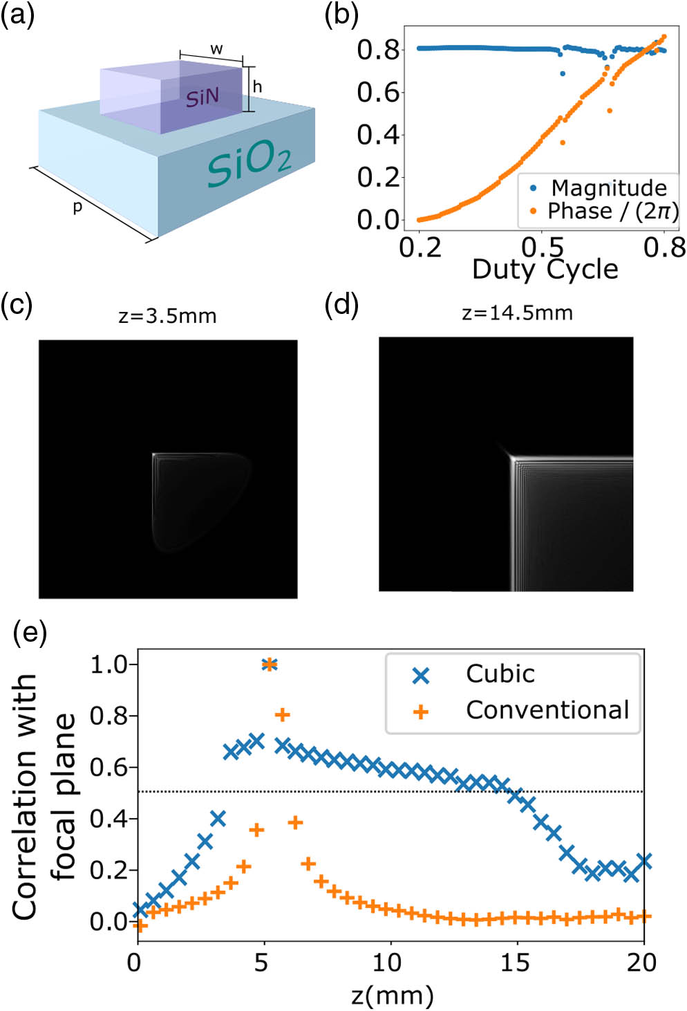
Figure 1.Scatterer and meta-optics design and simulation. (a) Schematic of
Figure 2 shows the optical and scanning electron microscopy (SEM) images of the fabricated EDOF meta-optic (the details of the fabrication can be found in Appendix A).
![]()
Figure 2.Images of the fabricated meta-optics. The meta-optic was sputter coated with gold-palladium alloy to ensure charge dissipation during imaging. (a) Optical image (scale bar is 150 μm) shows that the fabricated meta-optic is not centrosymmetric. (b) Scanning electron micrograph; scale bar of 1 μm taken at 45° to the normal.
3. MEASUREMENT
The meta-optic was mounted in a 1 cm diameter optic holder with standard C-mount threading for characterization. The PSF of the meta-optic was measured: a 25 μm diameter pinhole was used to approximate a point source, which was illuminated using a green (Thorlabs M530F1) light emitting diode (LED) with an optical bandwidth of
![]()
Figure 3.(a) Setup for PSF measurement. (b) Image of 25 μm pinhole. Image and object plane sweep. Illumination is using a 530 nm LED with 33 nm bandwidth.
We then tested our system by imaging a 1951 USAF resolution chart. The images of this backlit pattern were taken at various object
As a cubic EDOF meta-optic does not produce a lens-like PSF and the raw captured images do not resemble the object, the captured sensor data must be deconvolved to extract the in-focus image. Several different deconvolution routines, including Wiener, Richardson–Lucy, and learned methods, can be used to extract the image [19,20]. Here, we apply a routine based on total variation (TV) regularization to deconvolve and denoise the latent image [Fig. 4(a)]. This deconvolution method optimizes the sum of the gradient magnitudes while deconvolving the image [21]. As we are imaging under incoherent illumination, we can approximate the whole imaging process as a linear system if the camera is not saturated. We ensured that the intensity of the measured PSF did not exceed the maximum threshold of the camera to conserve the linearity of the measured PSF. We also assumed that the PSF was shift-invariant. This assumption breaks down for large lateral displacements of the pinhole, and taking multiple shifted PSFs while using a shift-variant deconvolution technique may produce better results [19]. In our work, this means we have a constrained field of view to ensure the shift-invariant property of our PSF. The imaging here shows the same range of tunable focal lengths as from the PSF measurements. We estimate the spatial resolution of our meta-optic via the linecuts from the measured patterns for an object (image) distance of 9.3 mm (13.1 mm) [Fig. 4(b)]. The first column shows the linecuts from the horizontal lines, and the vertical lines are shown in the second column. We can see that, for the horizontal lines, we can differentiate lines of thickness of
![]()
Figure 4.(a) Image of the airforce resolution chart for different image and object planes. The object distance is the separation between the transparency and the meta-optic while the image distance is the distance between the meta-optic and the camera. The object is illuminated via a 530 nm LED with 33 nm bandwidth (full width at half-maximum). (b) Linecut of the air force chart (for object distance of 9.3 mm and image distance of 13.1 mm) to estimate resolution: first column is for horizontal lines, and second column is for vertical lines. Top to bottom rows, group 5, number 4–6 for the airforce resolution chart.
Thus far in our experiments, we have used a microscope to relay the image produced by the EDOF meta-optic onto the sensor for imaging. With a larger aperture meta-optic, it is feasible to image directly onto an off-the-shelf camera module (E-con Systems See3CAM_10CUG). For integration, the meta-optic was mounted in a C-thread optic mount (Edmund Optics #63-979). The meta-optic was then attached to the camera module using a CS-mount, with a flange back distance of approximately 12 mm. The final package is shown in Fig. 5(a). In this configuration, the imaging system has a full diagonal field of view of 28°. We note that there are very few demonstrations of direct integration of visible meta-optics on sensors [22], primarily because many of the visible meta-optics have very small aperture
![]()
Figure 5.(a) Metasurface optic integrated with E-con Systems camera module. (b) Pictures of QR code object at differing object lengths taken by a singlet refractive lens with focal length 6 mm at
We tested the imaging capabilities of the EDOF camera and compared it to an off-the-shelf plano–convex F/2 refractive singlet with focal length 6 mm (Edmund Optics #32-952) by imaging a series of QR codes at different object distances. Both the EDOF meta-optic and refractive singlet lens are tested using the same camera module and with the same CS-mount, ensuring the same sensor characteristics and magnification. The QR codes are illuminated using a commercially available green LED ring light. The EDOF meta-optic and the refractive singlet have nominal focal lengths that are optimal for imaging at a finite conjugate distance of 13 mm. As seen in the Fig. 5(b), both imaging systems are fully capable of resolving the QR code, but the refractive singlet displays improved brightness and contrast when compared to the EDOF meta-optic. As we move the object plane further out, however, the difference between the EDOF meta-optic and refractive singlet widens. For object distances of 25 mm, 50 mm, and 80 mm, the refractive singlet is incapable of resolving the QR code, while the EDOF meta-optic reliably resolves the barcodes throughout the range of object distances. We note that this range is chosen arbitrarily to demonstrate the varifocal functionality of our EDOF meta-optics. The range can be increased by increasing the value of the parameter
When compared to our EDOF meta-optic (F/2.8, focal length 5.6 mm), the refractive singlet has a similar focal length (6 mm versus 5.6 mm) but a larger diameter (3 mm versus 2 mm). The superior brightness and contrast of the singlet at the object distance of 13 mm are attributed both to the larger diameter of the refractive singlet and also the properties of the EDOF meta-optic itself. At an aperture of 3 mm, the refractive optic has a surface that has twice the area of the EDOF meta-optic and is able to more than double the light collection. In addition, the EDOF meta-optic operates by sacrificing some contrast at the nominal object distance in favor of extending the depth of field significantly.
4. DISCUSSION
We reported an EDOF,
Our work opens opportunities for system-level integration of meta-optics with commercial sensors, and the simplification of tunable imaging systems exploiting EDOF properties. This new class of EDOF imaging systems could find applications in industrial production lines [24], compact image sensors, biological imaging [25,26], automobile navigation, and driver monitoring systems. Going beyond EDOF, such software-defined optics could potentially transfer many of the hardware functionalities to software and accelerate the co-design and co-integration of hardware and software for free-space optics.
Acknowledgment
Acknowledgment. The research is supported by Tunoptix and DARPA. A. M. is also supported by a Washington Research Foundation distinguished investigator award. Part of this work was conducted at the Washington Nanofabrication Facility/Molecular Analysis Facility, a National Nanotechnology Coordinated Infrastructure (NNCI) site at the University of Washington with partial support from the National Science Foundation.
APPENDIX A: FABRICATION METHODS
We used a 1.3 mm thick, 1 cm diameter silica mirror blank from Edmund Optics as a substrate. The choice of this wafer is motivated by its compatibility with commercial optical mounts. The double side polished silica wafer was cleaned in a boiling solution of sulfuric acid and hydrogen peroxide for 10 min. Plasma-enhanced chemical vapor deposition was then used to deposit a 633 nm layer of SiN on one side. A layer of 200 nm ZEP-520A positive tone electron-beam resist was spun after a short clean in oxygen plasma to maximize adhesion. An estimated 8 nm of Au/Pd was sputtered to dissipate charge produced from the electron beam. The pattern was written using electron-beam lithography (JEOL JBX6300FS at 100 kV). The Au/Pd layer was then subsequently removed by immersing in Transene Gold Etchant Type TFA with mild agitation. The resist was developed in Amyl acetate and rinsed in isopropyl alcohol, followed by a Descum process in a weak oxygen plasma. A layer of 50 nm nickel with a 5 nm chromium adhesion layer was then deposited using an electron-beam evaporator. Parts of the deposited Ni/Cr metal were removed by dissolving the supporting resist in a solvent while sonicating. An inductively coupled fluorine plasma etcher (Oxford Plasmalab 100) etched the exposed SiN down to the substrate, and the Ni/Cr metal hard mask was removed with nickel and chromium etchants. The metasurface was then cleaned again with a boiling solution of sulfuric acid and hydrogen peroxide for 10 min. Using direct write photolithography and electron-beam evaporation, a chromium aperture was patterned to block stray light from bypassing the meta-optics.
References
[1] S. W. Seo, S. Han, J. H. Seo, Y. M. Kim, M. S. Kang, N. K. Min, W. B. Choi, M. Y. Sung. Microelectromechanical-system-based variable-focus liquid lens for capsule endoscopes. Jpn. J. Appl. Phys., 48, 052404(2009).
[2] H.-S. Ee, R. Agarwal. Tunable metasurface and flat optical zoom lens on a stretchable substrate. Nano Lett., 16, 2818-2823(2016).
[3] S. M. Kamali, E. Arbabi, A. Arbabi, Y. Horie, A. Faraon. Highly tunable elastic dielectric metasurface lenses. Laser Photon. Rev., 10, 1002-1008(2016).
[4] E. Arbabi, A. Arbabi, S. M. Kamali, Y. Horie, M. Faraji-Dana, A. Faraon. MEMS-tunable dielectric metasurface lens. Nat. Commun., 9, 812(2018).
[5] Z. Han, S. Colburn, A. Majumdar, K. F. Böhringer. MEMS-actuated metasurface Alvarez lens. Microsyst. Nanoeng., 6, 79(2020).
[6] Z. Han, S. Colburn, A. Majumdar, K. F. Bohringer. Millimeter-scale focal length tuning with MEMS-integrated meta-optics employing high-throughput fabrication(2021).
[7] E. R. Dowski, W. T. Cathey. Extended depth of field through wave-front coding. Appl. Opt., 34, 1859-1866(1995).
[8] Z. Zalevsky. Extended depth of focus imaging: a review. SPIE Rev., 1, 018001(2010).
[9] R. K. Maia. Extended depth of focus IOLs: the next chapter in refractive technology?. J. Refract. Surg., 33, 146-149(2017).
[10] S. Banerji, M. Meem, A. Majumder, B. Sensale-Rodriguez, R. Menon. Extreme-depth-of-focus imaging with a flat lens. Optica, 7, 214-217(2020).
[11] S. M. Kamali, E. Arbabi, A. Arbabi, A. Faraon. A review of dielectric optical metasurfaces for wavefront control. Nanophotonics, 7, 1041-1068(2018).
[12] A. Zhan, S. Colburn, R. Trivedi, T. K. Fryett, C. M. Dodson, A. Majumdar. Low-contrast dielectric metasurface optics. ACS Photon., 3, 209-214(2016).
[13] S. Colburn, A. Zhan, A. Majumdar. Metasurface optics for full-color computational imaging. Sci. Adv., 4, eaar2114(2018).
[14] L. Huang, J. Whitehead, S. Colburn, A. Majumdar. Design and analysis of extended depth of focus metalenses for achromatic computational imaging. Photon. Res., 8, 1613-1623(2020).
[15] E. Bayati, R. Pestourie, S. Colburn, Z. Lin, S. G. Johnson, A. Majumdar. Inverse designed metalenses with extended depth of focus. ACS Photon., 7, 873-878(2020).
[17] W. T. Cathey, E. R. Dowski. New paradigm for imaging systems. Appl. Opt., 41, 6080-6092(2002).
[18] R. Pestourie, C. Pérez-Arancibia, Z. Lin, W. Shin, F. Capasso, S. G. Johnson. Inverse design of large-area metasurfaces. Opt. Express, 26, 33732-33747(2018).
[19] E. Tseng, S. Colburn, J. Whitehead, L. Huang, S.-H. Baek, A. Majumdar, F. Heide. Neural nano-optics for high-quality thin lens imaging. Nat. Commun., 12, 6493(2021).
[20] U. Akpinar, E. Sahin, M. Meem, R. Menon, A. Gotchev. Learning wavefront coding for extended depth of field imaging(2020).
[21] P. Getreuer. Total variation deconvolution using split Bregman. Image Process. Line, 2, 158-174(2012).
[22] B. Xu, H. Li, S. Gao, X. Hua, C. Yang, C. Chen, F. Yan, S. N. Zhu, T. Li. Metalens-integrated compact imaging devices for wide-field microscopy. Adv. Photon., 2, 026003(2020).
[23] S. R. M. Rostami, S. Pinilla, I. Shevkunov, V. Katkovnik, K. Egiazarian. Power-balanced hybrid optics boosted design for achromatic extended depth-of-field imaging via optimized mixed OTF. Appl. Opt., 60, 9365-9378(2021).
[24] . Liquid lenses in machine vision(2019).
[25] B. Forster, D. Van De Ville, J. Berent, D. Sage, M. Unser. Complex wavelets for extended depth-of-field: a new method for the fusion of multichannel microscopy images. Microsc. Res. Tech., 65, 33-42(2004).
[26] F. Aguet, D. Van De Ville, M. Unser. Model-based 2.5-D deconvolution for extended depth of field in brightfield microscopy. IEEE Trans. Image Process., 17, 1144-1153(2008).


Set citation alerts for the article
Please enter your email address

© Copyright 2018-2021 | Chinese Laser Press. All Rights Reserved 沪ICP备15018463号-20