Jianxun Xu, Ming Jiang, Yufa Chen. OFDM-based visible light communication with rotated polarity modulation aided complex color shift keying[J]. Chinese Optics Letters, 2019, 17(10): 100602
Copy Citation Text
High-rate techniques, such as optical orthogonal frequency division multiplexing (OFDM) and color shift keying (CSK), have been proposed for visible light communication (VLC). To fully exploit their advantages, in this Letter, we design a modulation scheme called rotated polarity modulation (RPM) aided complex CSK (CCSK) for OFDM-based VLC systems and derive its theoretical bit error rate and an optimal scaling factor. Analytical and simulation results show that in comparison to the existing schemes, the new RPM-CCSK-OFDM system offers an improved link performance and data rate under a modest complexity. It can also be applied to VLC systems equipped with different types of LED devices, thus enabling flexible deployments.
Visible light communication (VLC) is a promising technology that complements traditional radio frequency (RF) based wireless communication techniques. In VLC systems, intensity modulation/direct detection (IM/DD) are typically employed[1], where only real and positive optical signals can be transmitted and detected[2]. In recent years, it has been shown that VLC has a high potential to support high-speed indoor communication[3–5].
In order to increase the achievable data rate, optical orthogonal frequency division multiplexing (O-OFDM) has been proposed for VLC[6]. In orthogonal frequency division multiplexing (OFDM) based VLC systems, measures have to be taken for satisfying the real and non-negativity constraint on the signals. Hence, several O-OFDM schemes have been designed, such as the asymmetrically clipped O-OFDM (ACO-OFDM)[7], direct current (DC) biased O-OFDM (DCO-OFDM)[8], and unipolar OFDM (U-OFDM)[9]. On the other hand, color shift keying (CSK), which benefits from its multiplexing capability in color domains, also attracts increasing research interest[10,11] and has been adopted by the Institute of Electrical and Electronics Engineers (IEEE) 802.15.7 standard[12] as a high-rate option for VLC systems. Apart from the classical red–green–blue (RGB) LED or tri-LED (TLED)[12] techniques, which employ three color LEDs, the quad-LED (QLED) based CSK schemes utilizing four color LEDs have also been proposed[13].
Although CSK is capable of exploiting color diversity, similar to many other VLC-oriented techniques, it can only work in the unipolar non-negative real domain. In contrast, OFDM is able to utilize the degree of freedom (DoF) offered by the complex domain, but it cannot exploit color diversity. Such facts, therefore, lead to the motivation of combining both technologies for performance improvement, which, however, has not been fully investigated in the open literature.
Sign up for Chinese Optics Letters TOC. Get the latest issue of Chinese Optics Letters delivered right to you!Sign up now
Against this background, we propose to combine CSK with OFDM in order to fully exploit the available DoF in time, frequency, color, and complex domains, yielding a new hybrid system referred to as polarity modulation (PM) aided complex CSK (CCSK) OFDM. Based on our previously invented concept of PM-CCSK-OFDM[14], the new contributions in this Letter include the following. An improved scheme called RPM assisted CCSK-OFDM (RPM-CCSK-OFDM) is proposed, which further increases the minimum Euclidean distance (MED) of existing CCSK constellations[14], while reducing the demodulation complexity.A new bit error rate (BER) analysis model for both general CSK and CCSK schemes is developed and used to calculate the optimal scaling factor for RPM-CCSK constellations.The RPM-CCSK approach can be readily extended to QLED-based CSK, offering good flexibility and improved performance at high modulation orders.
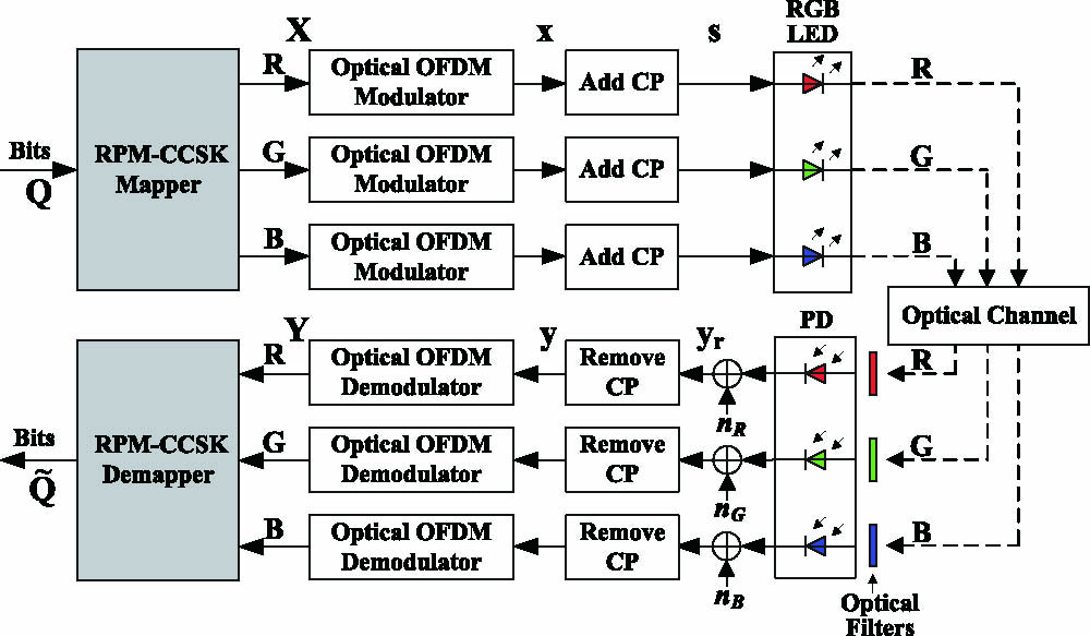
The schematic of the proposed RPM-CCSK-OFDM system is shown in Fig. 1, where TLED is employed as an example. The RPM-CCSK mapper converts the input bits to streams of complex-valued RPM-CCSK symbols that are subjected to the independent O-OFDM modulation operations, where also refers to the number of the color LEDs employed in the system, and we have for TLED. Note that due to the standalone symbol mapping process, most VLC-compatible O-OFDM techniques, such as ACO-OFDM, DCO-OFDM, and U-OFDM, can be employed in the proposed system. At the receiver, the three color signals are extracted from the composite light by the optical filters operating at the relevant wavelengths and then detected by the corresponding photodiodes (PDs), respectively. After O-OFDM demodulation, the bits are recovered by the RPM-CCSK demapper with maximum likelihood detection (MLD).
Figure 2 shows the structure of the RPM-CCSK mapper, which is constituted by a PM-CCSK module and an RPM module. As an example, in Fig. 2, we employ the RPM-MCCSK constellation of Fig. 3(b), where we set M = 4 with M being the CSK constellation order. For comparison purpose, our previously designed PM-4CCSK constellation[14] is plotted in Fig. 3(a). Note that the real or imaginary part of a legitimate 4CCSK symbol can take any of the eight points, depending on the specific combination of the CSK bits and the sign bit, as exemplified by the gray-colored parts in Fig. 2. More details on the rationale of the RPM-CCSK design will be given later.
Figure 2.Flowchart of the RPM-CCSK mapper using the RPM-4CCSK constellation of Fig. 3(b) as an example.
Let us now elaborate a little further on the RPM-CCSK mapper. Firstly, the input bits are grouped to a number of blocks, each constituted by an matrix . The parameter is the number of input RPM-CCSK symbols within one OFDM symbol, and is the number of bits per RPM-CCSK symbol, where denotes the number of bits in one conventional CSK symbol. The constant in refers to the two additional sign bits carried by an RPM-CCSK symbol.
For each column of , we further divide it into two parts. Each part includes CSK bits and one polarity bit. On the one hand, the CSK bits are forwarded to a conventional CSK mapper to produce a pair of color coordinates , which will be transformed to the intensities of the RGB light sources, together forming a conventional CSK symbol[12]. The polarity bit of ‘1’ or ‘0’, on the other hand, maps to the positive or negative sign of the real or imaginary component of that specific CSK symbol. For details of the PM-CCSK mapping process, we refer to Ref. [14]. Then, the two streams of signed real-valued CSK symbols output from the PM-CCSK module, which are referred to as PM-CCSK symbols and represented by matrices and , respectively, will be forwarded to the RPM module for the proposed rotation operation, as to be detailed next. Thus, two real-valued RPM-CCSK symbol sequences can be generated, which are then used as the real and imaginary parts of the complex symbols, respectively. Finally, the complex-valued RPM data matrix seen at the right hand side of Fig. 2 is produced.
The main differences between PM-CCSK[14] and the new RPM-CCSK schemes lie in the constellation design and the demodulation method.
An RPM-CCSK constellation is developed based on its PM-CCSK counterpart of the same order. Take again the 4-ary CCSK constellations of Fig. 3 as an example. To construct the RPM-4CCSK constellation, we need to follow three steps. Step 1: Rotation. With the aid of the polarity bit, a PM-CCSK constellation is divided into two sub-constellations, each representing a conventional CSK constellation, such as the 4CSK example seen in Fig. 3(a). Then, one of the sub-constellations is rotated 180° around the virtual axis represented by , where refer to the coordinate values of the color plane. In other words, an RPM-CCSK constellation is constructed in a way such that both of its sub-constellations are mirrored against the decision plane, as seen in Fig. 3(b).Step 2: Scaling. While keeping the centers of both sub-constellations fixed, scale both sub-constellations by a factor of on their respective planes.Step 3: Normalization. The coordinates of the signal points after scaling should be divided by a normalization factor to maintain the unit electrical power constraint.
More specifically, Step 1 is to obtain a constellation with mirrored symmetry for simplifying demodulation, while Steps 2 and 3 attempt to increase the MED of the CCSK constellation. In fact, in the existing PM-CCSK constellation design[14], the MED inside each CSK sub-constellation, , is much smaller than the distance, , between the two parallel sub-constellation planes of the CCSK constellation. Such a design deficit greatly restricts the achievable performance of conventional PM-CCSK systems. Hence, we propose to take the scaling and normalization operations in Steps 2 and 3 to increase at the cost of a slightly reduced . This offers significant performance gains by achieving the best tradeoff between and , thanks to the optimized scaling factor , which helps to minimize the BER of the system. Details on how to achieve will be given later.
At the conventional PM-CCSK receiver, MLD is employed to jointly recover the CSK and polarity bits. Naturally, MLD has a high computational complexity that increases exponentially upon the increase of the number of bits to be detected. Nonetheless, the associated complexity can be reduced by the proposed RPM-CCSK scheme, where the CSK and polarity bits are separately detected. More specifically, since the sub-constellations of the RPM-CCSK constellation are mirror symmetric against the decision plane , the polarity bit can be independently detected without affecting the detection on the CSK bits from the sub-constellations. Thus, MLD can be invoked to recover the CSK bits within one sub-constellation only, implying that only a halved number of points need to be tested in comparison to PM-CCSK. As a result, the computational complexity of an RPM-CCSK receiver is only 50% of that imposed by its PM-CCSK counterpart. Furthermore, the achievable BER performance of RPM-CCSK is also better than that of PM-CCSK, as to be detailed below.
Then, we can derive the BER formulas for PM/RPM-CCSK schemes over the additive white Gaussian noise (AWGN) channel. As a starting point, we first analyze the BER of conventional CSK. In the literature, an exact analysis approach[15] has been proposed, which however has no closed form and is too complicated for calculation, thus making it difficult to be applied to RPM-CCSK. Alternatively, approximated expressions[13,16] were developed at the cost of degraded accuracy. To strike for a better tradeoff, we propose an improved approximated BER formula for CSK as follows.
On the one hand, according to literature[17], the symbol error rate (SER) of CSK systems can be represented by , where denotes an -dependent function of , while is the electrical pseudo signal-noise ratio (pSNR)[17] in CSK systems, is the total optical power, and is the variance of electrical AWGN at each of the RGB channels. Note that is a constellation-dependent function. For typical CSK constellations, its expression can be found in literature[17]. On the other hand, since the average CSK symbol energy is proportional to [15], we may let , where is the average electrical energy of a CSK symbol given as . Thus, signal-to-noise ratio (SNR) at the virtual effective electrical receiver, if the RGB PDs are replaced by one equivalent single PD without optical filters, can be formulated as , where is the one-sided power spectral density of electrical AWGN. Therefore, the previously defined SER formula for CSK can be transformed to , where the values of are provided in Table 1.
Next, we discuss the relationship between BER and SER. For simplicity, we assume that only the errors occurring between adjacent constellation symbols are considered and that the error probabilities from any symbol to any of its adjacent neighbors are the same, denoted as . According to literature[18], we may derive the SER and BER of CSK systems as and respectively, where is the probability of the event that the th symbol is transmitted but wrongly detected as the th symbol , denotes the -dimensional vector containing the labelling bits for , is the Hamming distance between and , and the set has a cardinality of .
Inserting Eq. (1) into Eq. (2), we arrive at where is the average Hamming distance between two adjacent symbols in the CSK constellation. The values of for various CSK schemes are given in Table 1.
Now we analyze the BER performance of PM-CCSK and RPM-CCSK systems. Note that although the modulated symbols output from the RPM-CCSK module are complex, only their real (or imaginary) parts need to be considered, since the same CSK constellation is applied to both the real and the imaginary parts. Recall that the real part is modulated by one polarity bit and CSK bits. Denote as the BER of polarity bits. Assuming that the events of occurring polarity bit errors and CSK bit errors are statistically independent, the overall BER can be represented by where is given in Eq. (3).
In PM-CCSK, the polarity BER becomes very low at high SNR. In this case, Eq. (4) may be approximated as . In contrast, the polarity BER may not be ignored in RPM-CCSK, since becomes smaller than that in PM-CCSK due to constellation scaling and power normalization. Without loss of generality, we consider an RPM-CCSK constellation with . Thus, the polarity BER of RPM-CCSK may refer to the binary phase shift keying (BPSK) BER[19], denoted by where , denotes the function, and the average electrical symbol energy is given by where is the distance between the th point and the centroid of the CSK constellation, and is the average value of . Note from Eq. (6) that has changed from a constant in PM-CCSK to a function of in RPM-CCSK, which is one of the key differences due to scaling. Moreover, the scaling also changes the CSK SER formula [17] to a function of , yielding the CSK SER formula of RPM-CCSK as
The main CSK parameters are outlined in Table 1.
If we denote the energy per bit as , we have for the real (or imaginary) part, where . Therefore, similar to Eq. (4), we may formulate the RPM-CCSK system’s BER based on Eqs. (5), (7) by
As a next step, we discuss the optimization of for RPM-CCSK. From Eq. (8), we note that is a function of and . Thus, by exploiting Eq. (8), we define the following objective function: which can be solved by MATLAB’s functions “diff” and “solve”. Figure 4(a) shows that when increases, converges to certain values for different RPM-CCSK schemes. Moreover, Fig. 4(b) reveals that although varies, especially at low levels, the selection of the converged values indicated by the horizontal lines in Fig. 4(a) would not result in significant degradation of BER. Hence, in the sequel, the three converged values , , and are chosen for in the respective CSK schemes regardless of . Note that was used to plot Fig. 3(b).
Aiming to show the benefits of the proposed scheme, we provide a range of simulation results in the sequel assuming an AWGN channel. For fair comparison, we set subcarriers and select color band combination one (CBC-1)[12] for all schemes investigated.
In Fig. 5(a), we compare the theoretical BER of CSK generated by Eq. (3) with those by existing schemes[13,15,16]. The results show that our method matches the simulated results better than existing approximate methods[13,16] and is only a little worse than the exact method[15] at low levels. However, the exact method[15] has two major deficiencies. On the one hand, it requires complicated geometrical analyses and parameter calculations, making it much more challenging to be reproduced in comparison to our method, which provides a simple closed-form expression with determinative parameters. For the same reason, the exact method is difficult to be adapted for deriving the BER of RPM-CCSK. On the other hand, its time complexity is as high as , since it has to calculate errors occurring between any pair of constellation symbols. In contrast, our method is benefitted from the simplified integral calculation of in Eq. (3) for CSK, which results in a low complexity of only. In fact, our method offers an easy-to-implement solution, with sufficient accuracy in the typically more interesting medium-to-high SNR range, as proved by Fig. 5(a).
Figure 5.Theoretical (T) and simulated (S) BER of: (a) conventional CSK, (b) PM-CCSK-ACO-OFDM, and (c) RPM-CCSK-ACO-OFDM.
Next, we evaluate the hybrid CCSK-OFDM system’s performances based on PM and RPM mechanisms. Recall that O-OFDM always brings an inherent power loss in comparison to RF-OFDM, resulting in a loss factor on . Taking RPM-CCSK-OFDM as an example, its BER expression may be borrowed from Eq. (8), though it needs to be modified as . The value of depends on the specific O-OFDM scheme used. Without loss of generality, we choose ACO-OFDM as an example, while other O-OFDM schemes are also applicable. For ACO-OFDM, an additional 3 dB power is required when compared with its bipolar RF counterpart OFDM system using the same constellation[20], implying . Figures 5(b) and 5(c) compare the theoretical and simulated BERs in the context of PM/RPM-CCSK-ACO-OFDM systems, respectively, where a good match is observed.
Furthermore, in Fig. 6(a), we show that RPM-CCSK-ACO-OFDM outperforms its PM-based counterpart, especially at higher modulation orders. In Fig. 6(b), we compare the RPM-4CCSK scheme with the conventional bipolar 64-ary quadrature amplitude modulation (64QAM) aided scheme based on ACO/DCO/U-OFDM, assuming a peak data rate of bits per symbol (BPS). A DC bias of 13 dB was applied to DCO-OFDM. The superior results indicate the benefits of our scheme, which not only effectively compensates the usual halved spectral efficiency (SE) in O-OFDM in comparison to RF-OFDM, but also offers an additional performance gain, thanks to the new RPM mechanism introduced.
Figure 6.BER comparison of the various schemes investigated (‘A,’ ACO-OFDM; ‘D,’ DCO-OFDM; ‘U,’ U-OFDM).
It is worth pointing out that RPM-CCSK can readily be extended to systems employing different kinds of LEDs, such as the QLED[13]. Following a similar design procedure described in previous sections, we may apply appropriate BER expressions[16] to Eq. (3) to obtain the parameter values for QLED-based CSK systems, as shown in Table 1.
Last but not least, in Fig. 7, we compare the various CCSK-OFDM schemes in terms of computational complexity, which is defined as the total number of real multiplications and real additions required for demodulation. It can be seen that although having a higher demodulation complexity compared with the conventional QAM system, the proposed RPM scheme significantly reduces the complexity of the PM arrangement.
Figure 7.Computational complexity of various OFDM schemes.
In conclusion, in this Letter the so-called RPM-CCSK-OFDM scheme is proposed. Based on the new BER derivation method for PM/RPM-CCSK, an optimized scaling factor minimizing the achievable BER performance can be obtained. Results prove the accuracy of the theoretical BER and the benefits of the new scheme, including performance, complexity and flexibility.
[11] S. Chen, C. Chow. IEEE Photon. J., 6, 7904106(2014).
[12] IEEE Standard for Local and Metropolitan Area Networks--Part 15.7: Short-Range Wireless Optical Communication Using Visible Light. IEEE Std 802.15.7-2011(2011).
[16] R. Singh, T. O’Farrell, J. P. R. David. 2015 IEEE 26th Annual International Symposium on Personal, Indoor, and Mobile Radio Communications (PIMRC), 575(2015).
Jianxun Xu, Ming Jiang, Yufa Chen. OFDM-based visible light communication with rotated polarity modulation aided complex color shift keying[J]. Chinese Optics Letters, 2019, 17(10): 100602