Songtao Yang, Bo Chen, Bin Lin, Xiangqun Cao. Filament diameter measurement system based on dual diffraction[J]. Chinese Optics Letters, 2015, 13(12): 120501
Copy Citation Text
This Letter proposes a brand-new filament diameter measurement method based on what is called “dual diffraction,” in that a grating is added behind the filament to make full use of its subdivision and amplification characteristics. Higher measurement accuracy is achieved by this method compared with the traditional diffraction method. To verify its accuracy, three standard filaments with nominal values of 100.2, 120.1, and 140.8 μm are measured by the dual diffraction method and traditional diffraction method under the same experimental conditions. The relative measurement errors of the new method are less than 0.75%, and its average relative error is reduced by 56% compared with the traditional diffraction method.
The diameter measurement of a filament plays a vitally important role in laboratory studies and microprocessing technology, especially in micro-machines, biological equipment, optical processing, textiles, and other applications in various areas in the industry[1], where accurate measurement is required on such occasions to make sure of the quality of products. Depending on whether the filament is contacted or not, methods for filament diameter measurement can be classified as contact and noncontact. Contact methods have already been highly developed and are applied on occasions that require less precision, including the winding method, the micrometer method, the bowstring method, the three coordinate measurement method, and so on. On the other hand, noncontact methods include the weighing method and optical detection methods such as the microscope measurement, the projection imaging method, the interferometry method, the diffraction method, the structured-light vision method, and so on[2–4].
As the focus of this Letter, the diffraction method is a kind of noncontact method that can achieve better performances compared with contact methods. The diffraction method has been proved to be able to overcome the shortcomings of contact methods, including deformation and low accuracy. As a matter of fact, the diffraction method has achieved accurate measurements on very thin filaments with small errors, thus meeting the requirements for many occasions.
The current research on the diffraction measurement of a filament diameter runs into two directions. One direction is the modification of the filament diffraction formula[5–8], and the other involves methods of effective information extraction from the filament diffraction spectrum[9–11]. These two directions are both a continuation of the traditional diffraction method. In this Letter, a brand-new filament diameter measurement method is proposed based on what is called the “dual diffraction method,” where a grating is added behind the filament to make full use of its subdivision and amplification characteristics. It is shown that a higher measurement accuracy is achieved by this method compared with the traditional diffraction method.
Sign up for Chinese Optics Letters TOC. Get the latest issue of Chinese Optics Letters delivered right to you!Sign up now
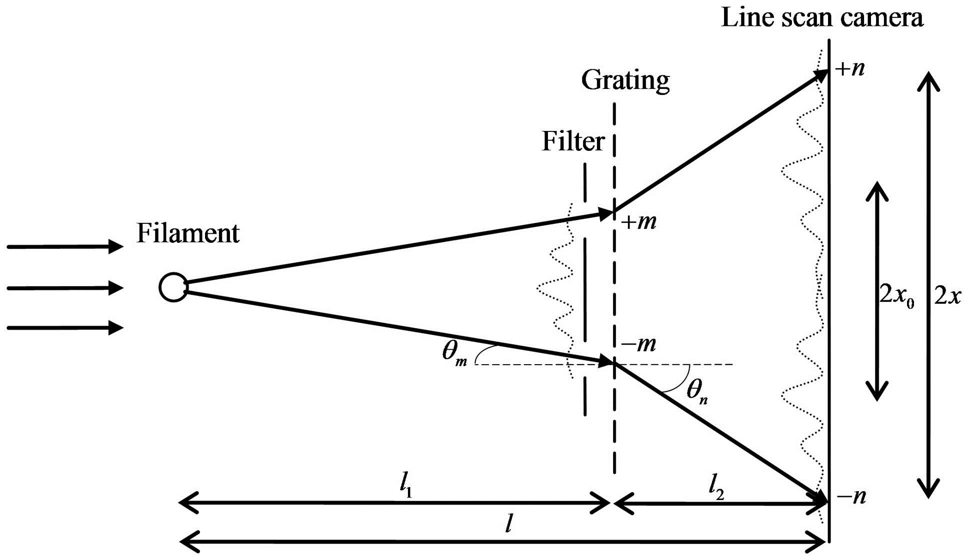
A traditional diffraction system can be constructed by removing the filter and the grating shown in Fig. 1, and the diffraction spectrum of the filament is measured by a line scan camera. The diameter of filament is calculated by the average spacing between adjacent dark stripes , as follows: where is the distance between the filament and the line scan camera, and is the wavelength of the light source.
In contrast, it is the bright stripes spacing that is measured in the “dual diffraction method.” The schema and setup of a filament diameter measurement system based on dual diffraction are shown in Figs. 1 and 2. The filament and the grating are diffraction components, thus, it is named “dual diffraction.” In the system, parallel monochromatic light is diffracted by the filament at first and the light is filtered by the filter, which allows only bright stripes of orders to pass through. Then, the through-passed bright stripes are diffracted by the grating for the second time, and the final diffraction spectrum will be detected by the line scan camera.
Figure 2.Setup of a filament diameter measurement system based on dual diffraction.
The filament’s diffraction angle of the -order bright stripe in Fig. 1 meets the following condition: where is the -th positive solution of transcendental equation , whose positive solution set is .
After being diffracted by the grating behind the filter, the bright stripes of orders are amplified. The departure angle of grating diffraction can be calculated by the grating equation , as follows: where is the grating constant, and is the order of grating diffraction. Therefore, the spacing between the grating diffraction’s -th stripe of the diameter diffraction’s -th bright stripe and the grating diffraction’s -th stripe of the diameter diffraction’s -th bright stripe is where is the distance between the filament and the grating, and is the distance between the grating and the line scan camera. Then the equation for diameter measurement based on double gratings is obtained by substituting Eqs. (2) and (3) into Eq. (4), as follows: The analytical solution of filament diameter cannot be obtained by this equation, so numerical methods such as the bisection method and the iteration method should be used.
In the case of the traditional direct filament diffraction without using the grating, the spacing between bright stripes of orders is
Hence, the magnification of the dual diffraction method compared with the traditional diffraction method on the filament diameter measurement is The theoretical values of magnification for different and are shown in Table 1, with , the filament diameter , the wavelength , and the grating constant .
m
n
1
2
3
4
5
6
7
8
1
2.74
2.02
1.72
1.55
1.45
1.38
1.33
1.29
2
4.51
3.04
2.44
2.12
1.91
1.77
1.67
1.59
3
6.27
4.07
3.17
2.69
2.38
2.17
2.01
1.89
4
8.06
5.11
3.91
3.26
2.85
2.56
2.36
2.20
5
9.87
6.16
4.66
3.84
3.33
2.97
2.71
2.51
6
11.71
7.24
5.43
4.44
3.81
3.38
3.07
2.83
7
13.59
8.33
6.21
5.05
4.31
3.81
3.44
3.16
8
15.51
9.46
7.01
5.67
4.82
4.24
3.82
3.49
9
17.48
10.61
7.83
6.31
5.35
4.69
4.21
3.84
10
19.51
11.80
8.68
6.97
5.90
5.15
4.61
4.20
Table 1. Theoretical Values of Magnification for Different m and n
It is observed from Table 1 that a higher grating diffraction order achieves a larger magnification when the filament diffraction order stays unchanged, and a lower filament diffraction order achieves a larger magnification when the grating diffraction order stays unchanged. Therefore, a large magnification requires small and large ; however, errors will also be amplified by the system if a large magnification is chosen. Further, accuracy is not able to be significantly improved if a small magnification is chosen. In addition, the size of the line scan camera is required to be longer when the spacing of the bright stripes is amplified. Thus, an appropriate tradeoff of and needs be made.
The line scan camera in the experiment is produced by Teledyne DALSA, Inc.; it is the model P3-80-16K40-00-R, whose resolution is , pixel size is 3.5 μm, and total length is 57.344 mm. The light source in the system was an He–Ne laser with a wavelength of 632.8 nm. The grating’s constant value is 20 μm. The distance from the filament to the grating and the distance from the grating to the line scan camera were respectively measured as and , which meet the Fraunhofer diffraction condition . In fact, and are all measured by the diffraction grating. Before setting up the filament and the filter, the grating was laid on the position of the filament and the grating shown in Fig. 1. The diffraction spectrum was measured by the line scan camera to calculate the distances and by the grating constant and stripes spacing using the grating equation. Thus, could also be calculated by .
As the fact that the effective measurement range is limited by the camera’s total length, it is not proper to choose too large a magnification, which would have led to large spaces between the stripes. Furthermore, it is also not proper to choose a small , for the reason that the grating diffraction spectrum of the order filament diffraction and the grating diffraction spectrum of the order filament diffraction would overlap, so that the stripes’ information could not be extracted correctly. After these considerations, was chosen in the experiment.
The filaments used in the experiment were produced by Chengdu Chengliang Tools Group Co., Ltd. The respective factory nominal values of diameter were 100, 120, and 140 μm, with a grade of tolerance of . To get more accurate values of these filaments, they were all additionally measured by a Digital Microscope VHX-5000 under magnification, which is produced by the Keyence Corporation. The diameter was measured in different positions for each filament, and the average value was taken as the standard diameter. The measurement values of each filament were 100.2, 120.1, and 140.8 μm. The results showed that the differences caused by uneven manufacturing on different locations for each filament did not exceed .
The experiments are conducted on the filaments using the dual diffraction method and the traditional method. To make sure that the experimental conditions were kept the same when applying these two methods, the traditional method experiments were conducted by merely removing the filter and grating in the dual diffraction system shown in Fig. 1 and the calculations were done with Eq. (1). Therefore, the distance between the filament and the line scan camera in the traditional diffraction method was equal to the dual diffraction system, namely .
Figures 3 and 4 show the spectrum of a 100.2 μm filament measured by the line scan camera in the dual diffraction system and the traditional diffraction system, respectively. An identical algorithm was applied to find the locations of each bright or dark stripe. Then, the diameter of the filament was calculated by the spacing of the corresponding stripes. The steps in detail are as follows: Butterworth low-pass filter with the same cut-off frequency was applied to filter the raw diffraction spectrum data to remove noises.Quadratic polynomial fit, which takes a certain number of data points as the fit width, was applied to find the approximate positions of the bright or dark stripes by scanning the spectrum of the diffraction. Then, the quadratic polynomial fit was applied again to find the accurate position of each stripe. The centers of the data points used in the second quadratic fit were exactly those approximate positions found in the first fit, and the fit width was kept the same.For the dual diffraction spectrum shown in Fig. 3, the positions of the grating diffraction’s -th stripe of the diameter diffraction’s -th bright stripe and the grating diffraction’s -th strip of the diameter diffraction’s -th bright stripe were located by scanning the bright stripes from the diffraction center to each side. The diameter of the filament was calculated by spacing a distance of the stripe and the stripe using Eq. (5) along with the bisection method. For the traditional diffraction spectrum shown in Fig. 4, the second and the 10th dark stripe was located at each side of the spectrum and the spacing distance between them was 8 times the spacing between the adjacent dark stripes, . We took the average of on each side and calculated the diameter of the filament using Eq. (1).
Figure 3.Diffraction of dual diffraction method measured by line camera (100.2 μm).
Each filament was measured through the steps above 10 times, and the measurement results are shown in Table 2, where is the average diameter of 10 measurements, is the variance, is the absolute error, and is the relative error. It is observed that the measurement error of the dual diffraction method is smaller than the traditional diffraction method, for its average relative error is 0.68%, reduced by 56% compared to the traditional diffraction method’s error of 1.53%. The maximum relative measurement error of this method is less than 0.75%. It can also be shown that the measurement stability of the dual diffraction method is better for smaller variances.
Dual Diffraction Method
Traditional Diffraction Method
Nominal Diameter a0/μm
aavg/μm
σ
Δa/μm
Δa/a0 (%)
aavg/μm
σ
Δa/μm
Δa/a0 (%)
100.2
99.5
0.0006
0.7
0.70
102.4
0.0017
2.2
2.30
120.1
121.0
0.0004
0.9
0.75
121.8
0.0020
1.7
1.42
140.8
141.6
0.0012
0.8
0.58
142.0
0.0036
1.2
0.86
Average
–
0.0007
0.8
0.68
–
0.0024
1.7
1.53
Table 2. Comparison of Measurements by the Dual Diffraction Method and the Traditional Method
In conclusion, this Letter proposes a brand-new filament diameter measurement method based on what is called “dual diffraction,” in that a grating is added behind the filament. Experiments on three standard filaments with nominal values of 100.2, 120.1, and 140.8 μm show that the “dual diffraction” method is able to achieve better accuracy and stability than the traditional diffraction method.
Songtao Yang, Bo Chen, Bin Lin, Xiangqun Cao. Filament diameter measurement system based on dual diffraction[J]. Chinese Optics Letters, 2015, 13(12): 120501