
Pierre-Marie Dalbies, Sandy Cavaro, Edouard Bordenave, Nathalie Blanchot, Julien G. Moreau, Jérôme Neauport. Analysis of mid-spatial frequency wavefront distortions from a liquid-cooled flash-lamp pumped Nd:phosphate laser amplifier[J]. High Power Laser Science and Engineering, 2024, 12(1): 010000e3
- High Power Laser Science and Engineering
- Vol. 12, Issue 1, 010000e3 (2024)
Abstract
1 Introduction
High-power laser facilities can be mostly divided into two classes of systems[1], with (i) energetic/low-repetition-rate systems on one hand for facilities, such as the National Ignition Facility (NIF)[2] or Laser Megajoule (LMJ)[3], and (ii) low-energy/high-power/high-repetition-rate systems on the other hand[4–6]. However, the past decade has been marked by numerous efforts to populate the intermediate 100 J to kJ energy/high-power/high-repetition-rate class. L3-HAPLS[7], DIPOLE[8] and L4-ATON[7] are the first laser facilities in this latter category. These laser systems were developed to provide new directions for high-energy laser–matter interaction experiments due to the significant increase in experimental data generated; however, a renewed interest has recently been driven by NIF fusion shots[9–11] that underscore the need for high-energy/high-repetition-rate laser facilities that could open the route towards inertial fusion energy (IFE). Heat management is at the core of these energetic recurrent systems, particularly during the amplification of the laser beams. Different thermal management technologies have been investigated, including cryogenic cooling[8], high-speed gas-flow[12] and liquid cooling[13,14]. Liquid cooling offers a relatively simple and cost-effective solution for heat extraction[15], but several difficulties have to be addressed. The coolant must be transparent at both pump and emission wavelengths, have a low absorption to reduce losses, a weak nonlinear index of refraction and ideally have a broad compatibility with materials, including the amplifier medium, as well as presenting a low hazard to facilitate implementation[16]. From an optical point of view, liquid cooling channels need to induce small optical aberrations from large period (power, astigmatism, …) down to mid and small spatial millimeter-scale periods[17,18]. Liquid-cooled amplifiers are currently used in facilities as pump laser or main beam amplifiers[7,19,20], which has motivated developments for improving their performances. In particular, (i) a thermo-hydraulic-mechanical-optical model was developed to provide a complete and multi-physics model of these amplifiers[21]. During the first step, the gain and heat generated by optical pumping are calculated using a combination of a phenomenological lamp model[22], heat transport and calculation of the population of the different atomic levels. In the second step, the spatial distribution of the heat is used in a COMSOL software model that includes the computer-aided design of the amplifier cell and the description of the coolant flow to compute by ray tracing the laser wavefront deformation induced by thermo-mechanical-hydraulic effects[21]. (ii) A liquid-cooled amplifier test-bed was designed and built to characterize mid- to large-scale spatial frequency distortions in amplified wavefronts and compare these with model predictions[23]. In addition, knife-edge Foucault measurements were also performed in a single-pass configuration to investigate (0.1–10 mm) small- to mid-scale spatial frequency distortions, in particular those induced by liquid flow[24]. Here we report on the amplified optical wavefront performances in the mid- to large-spatial-scale range (1–100 mm) of a neodymium phosphate liquid-cooled amplifier cell pumped by flash-lamps built as a test-bed for liquid-cooled amplification. The amplifier cell was qualified at different repetition rates from 1 shot per few minutes to 1 shot per minute. Emphasis is herein placed on assessment of the mid-spatial-scale (1–10 mm) distortions in amplified wavefronts commonly observed in fluid-cooled amplifiers[25,26]. Such wavefront defects in large-aperture multi-slab laser systems are likely to degrade the focal point quality and, in the worst case, damage optical materials due to Kerr effects and/or amplitude modulation during laser beam propagation[17,27].
2 Experiment setup
The amplifier cell consists of two 120 mm × 215 mm 10 mm thick Hoya-cladded LHG-8 neodymium-doped laser slabs (the Nd doping density of
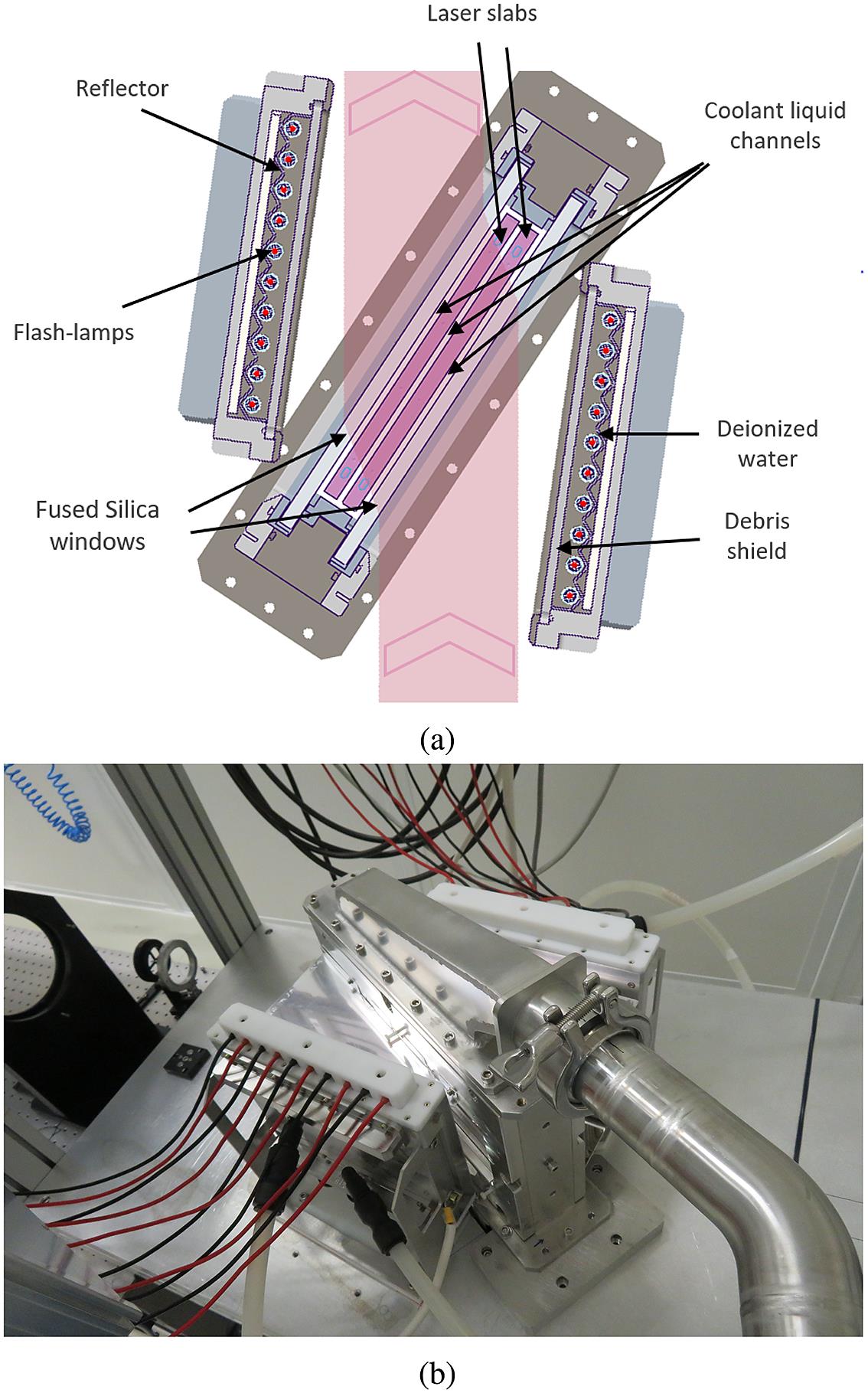
Figure 1.(a) Schematic of the liquid-cooled split-slab amplifier cell. The pink vertical line represents the laser beam. (b) Photo of the assembled amplifier.
![]()
Figure 2.(a) Experimental setup used to characterize the amplifier in a four-pass configuration. The gain is measured using photo-diodes (PDs). Spatial distribution of gain is measured on a CCD camera. Wavefront distortion is measured with an HASO wavefront analyzer. (b) Single-pass gain distribution of the clear aperture of 90 mm × 90 mm (1 shot/min, 29 L/min). A gain average of 1.151 is obtained with a standard deviation of 0.013 over the 90 mm × 90 mm area.
3 Results and discussion
The gain of the amplifier cell was measured in a four-pass configuration at a repetition rate of 1 shot per minute and 1200 A was applied to the flash-lamps during 500 μs with a power supply cut-off after the peak gain emission. We report a gain of
Sign up for High Power Laser Science and Engineering TOC. Get the latest issue of High Power Laser Science and Engineering delivered right to you!Sign up now
The liquid flow multi-slab amplifier cell can induce mid- to high-frequency spatial wavefront distortions without amplification. As a guideline for large inertial confinement fusion (ICF) lasers, typical values of 2.5 nm root mean square (RMS) in the (1–10 mm) range for the transmitted wavefront are usually considered as an acceptable upper limit for individual amplifier slabs; in addition, a 1D power spectral density (PSD) specification in the form of
We now benefit from this recent advance in monitoring and analyzing wavefront defects during amplified shots at different repetition rates and coolant speed flows. Wavefront measurement is performed using HASO equipment, which is simple to implement and offers the ability to limit the spatial scale to approximately 1 mm and above, a range of period likely to be modified by the liquid flow.
Table 1 presents the wavefront data obtained during a shot sequence of 1 h at repetition rates of 1 shot per minute, 1 shot every 2 and 5 min, and for coolant flow speeds of 15, 29 and 40 L/min (corresponding respectively to fluid velocities of 0.09, 0.18 and 0.25 m/s in the liquid channels). Although reducing the flow rate further would reduce mid-spatial-scale distortions, that is, in the limit of no flow minimal mid-scale spatial distortion would be observed, the impact on larger scale distortions would be detrimental. Table 1 also presents the data without amplification, labeled 0/min to demonstrate the contribution due solely to the coolant flow at these different flow rates. Samples of the transmitted wavefront maps measured over a 1 h sequence are presented in Figure 3 for a flow rate of 29 L/min and repetition rate of 1 shot per minute. We note from Table 1 that large-scale wavefront defects associated with periods of more than 10 mm are slightly minimized in terms of the peak-to-valley (PV) and RMS slope when reducing the repetition rate from 1 shot per min down to 1 shot every 5 min. However, the amplitude of this reduction is rather small, of the order of 10–20 nm in PV. In terms of the amplified transmitted wavefront PV and RMS slope, these values are stable and therefore likely to be corrected by an improved mechanical mounting of the slabs and/or a deformable mirror. For the 29 L/min measurements, we were unable to carry out the experiments at each repetition rate in succession, imposing some readjustments of the amplifier cell. These readjustments affected the PV value of large-scale wavefront distortions by between 10 and 20 nm, and were responsible for the anomaly observed in the PV and RMS slope for this coolant rate; however, it did not affect the RMS (1–10 mm) since this is mostly induced by mid-scale coolant flow distortions. Regarding mid-spatial periods over the (1–10 mm) range, a clear reduction of the RMS is evidenced when reducing the repetition rate, but this quantity is mostly independent of the flow rate. We also note that in the whole range of parameters considered, the RMS in the (1–10 mm) band remains smaller than 2.5 nm (typical amplifier slab specification). Moreover, whatever the quantity considered, the flow rate and the repetition rate, amplification degrades wavefront distortion compared to the sole contribution of the coolant (labeled 0/min in Table 1).
| RMS slope | RMS | ||
|---|---|---|---|
| PV (nm) | [1–10 mm] (nm) | ||
| 15 L/min | |||
| 1/min | 161 (16) | 3 (0.3) | 1.03 (0.15) |
| 1/2 min | 150 (9) | 2.8 (0.1) | 0.95 (0.06) |
| 1/5 min | 140 (10) | 2.6 (0.2) | 0.9 (0.03) |
| 0/min | 125 (10) | 2 (0.1) | 0.80 (0.02) |
| 29 L/min | |||
| 1/min | 165 (14) | 3.1 (0.3) | 1.08 (0.18) |
| 1/2 min | 141 (9) | 2.4 (0.1) | 1 (0.09) |
| 1/5 min | 150 (5) | 2.9 (0.1) | 0.96 (0.03) |
| 0/min | 128 (11) | 2 (0.1) | 0.77 (0.02) |
| 40 L/min | |||
| 1/min | 168 (14) | 3.2 (0.3) | 1.16 (0.23) |
| 1/2 min | 155 (10) | 2.9 (0.2) | 0.99 (0.06) |
| 1/5 min | 153 (7) | 2.9 (0.1) | 0.95 (0.03) |
| 0/min | 125 (10) | 2.1 (0.1) | 0.79 (0.02) |
Table 1. Transmitted amplified wavefront distortions at flow rates of 15, 29 and 40 L/min for repetition rates of 0 and 1 shot per minute, 1 shot every 2 and 5 min expressed in peak-to-valley (PV), root mean square (RMS) slope for periods above 10 mm and RMS in the (1–10 mm) range. The 0/min data correspond to the case without amplification. Wavefront measurements over a clear aperture of 90 mm × 90 mm. Values in parenthesis represent the standard deviation over a shot sequence of 1 h.
![]()
Figure 3.Spatial distribution of the amplified transmitted wavefront along a 1 h sequence at 1 shot per minute, flow rate of 29 L/min, as measured with the wavefront analyzer. A great stability of the wavefront is obtained with an RMS of less than 0.08% for the PV value over the whole sequence (see
To get a better understanding of the mid-spatial periods, we present in Figure 4 the minimum-to-maximum envelope of the PSD calculated from the amplified wavefront acquisitions over a sequence at 29 L/min with the repetition rates of 1 shot/min, 1 shot/2 min, and 1 shot/5 min. The frequency cut-off at 0.7 mm−1 is due to the resolution of the HASO camera. We observe that increasing repetition rate from 1 shot/5 min to 1 shot/min increases frequency defects above few millimeters. Such distortions are induced by the coolant flow, as reported in Refs. [24, 25]. However, whatever the repetition rate tested, the PSD stays below the acceptable upper limit represented by the broken purple line.
![]()
Figure 4.One-dimensional PSD over the (1–10 mm) range calculated from the wavefront measurements. Each envelope represents the minimum-to-maximum PSD variation along a 1 h sequence at a flow rate of 29 L/min for repetition rates of 1 shot/min, 1 shot/2 min and 1 shot/5 min, respectively. The purple dashed line is a guide to the eye representing a typical PSD specification for ICF laser slabs[17,18].
4 Conclusion
In summary, we have designed a split-slab liquid-cooled amplifier equivalent to a laser slab. This cooled slab amplifier exhibits low wavefront distortions at mid-spatial frequencies (amplitude and PSD) and stable gain at repetition rates up to 1 shot per minute. The remaining mid-spatial distortions are mostly induced by the coolant flow. Such cooled slabs could be implemented in large high-energy systems requiring on-target focusing performance.
References
[1] C. N. Danson, C. Haefner, J. Bromage, T. Butcher, J.-C. F. Chanteloup, E. A. Chowdhury, A. Galvanauskas, L. A. Gizzi, J. Hein, D. I. Hillier. High Power Laser Sci. Eng., 7, e54(2019).
[2] J. Di Nicola, T. Bond, M. Bowers, L. Chang, M. Hermann, R. House, T. Lewis, K. Manes, G. Mennerat, B. MacGowan, R. Negres, B. Olejniczak, C. Orth, T. Parham, S. Rana, B. Raymond, M. Rever, S. Schrauth, M. Shaw, M. Spaeth, B. Van Wonterghem, W. Williams, C. Widmayer, S. Yang, P. Whitman, P. Wegner. Nucl. Fusion, 59, 032004(2018).
[3] V. Denis, J. Néauport, N. Blanchot, C. Lacombe. Proc. SPIE, 12401, 1240102(2023).
[4] H. Kiriyama, A. S. Pirozhkov, M. Nishiuchi, Y. Fukuda, K. Ogura, A. Sagisaka, Y. Miyasaka, H. Sakaki, N. P. Dover, K. Kondo, H. F. Lowe, A. Kon, J. K. Koga, T. Z. Esirkepov, N. Nakanii, K. Huang, M. Kando, K. Kondo. High Energy Density Phys., 36, 100771(2020).
[5] C. Radier, O. Chalus, M. Charbonneau, S. Thambirajah, G. Deschamps, S. David, J. Barbe, E. Etter, G. Matras, S. Ricaud, V. Leroux, C. Richard, F. Lureau, A. Baleanu, R. Banici, A. Gradinariu, C. Caldararu, C. Capiteanu, A. Naziru, B. Diaconescu, V. Iancu, R. Dabu, D. Ursescu, I. Dancus, C. Alexandru, K. A. Tanaka, N. V. Zamfir. High Power Laser Sci. Eng., 10, e21(2022).
[6] K. Nakamura, H.-S. Mao, A. J. Gonsalves, H. Vincenti, D. E. Mittelberger, J. Daniels, A. Magana, C. Toth, W. P. Leemans. IEEE J. Quantum Electron., 53, 1200121(2017).
[7] F. Condamine, N. Jourdain, D. Kramer, P. Trojek, A. Gintrand, G. Fauvel, P. Pandikian, J. Bartoníček, G. Friedman, M. Havlík, J.-C. Hernandez, J. Hubáček, T. Laštovička, V. Orna, O. Renner, P. Rubovič, B. Rus, R. L. Singh, Š. Vyhlídka, S. Weber. Plasma Phys. Controll. Fusion, 65, 015004(2022).
[8] P. Mason, M. Divokỳ, K. Ertel, J. Pilař, T. Butcher, M. Hanuš, S. Banerjee, J. Phillips, J. Smith, M. De Vido, A. Lucianetti, C. Hernandez-Gomez, C. Edwards, T. Mocek, J. Collier. Optica, 4, 438(2017).
[9] A. Zylstra, A. Kritcher, O. Hurricane, D. Callahan, K. Baker, T. Braun, D. Casey, D. Clark, K. Clark, T. Döppner, L. Divol, D. E. Hinkel, M. Hohenberger, C. Kong, O. L. Landen, A. Nikroo, A. Pak, P. Patel, J. E. Ralph, N. Rice, R. Tommasini, M. Schoff, M. Stadermann, D. Strozzi, C. Weber, C. Young, C. Wild, R. P. J. Town, M. J. Edwards. Phys. Rev. Lett., 126, 025001(2021).
[10] A. Kritcher, A. Zylstra, D. Callahan, O. Hurricane, C. Weber, D. Clark, C. Young, J. Ralph, D. Casey, A. Pak, O. L. Landen, B. Bachmann, K. L. Baker, L. B. Hopkins, S. D. Bhandarkar, J. Biener, R. M. Bionta, N. W. Birge, T. Braun, T. M. Briggs, P. M. Celliers, H. Chen, C. Choate, L. Divol, T. Döppner, D. Fittinghoff, M. J. Edwards, M. Gatu Johnson, N. Gharibyan, S. Haan, K. D. Hahn, E. Hartouni, D. E. Hinkel, D. D. Ho, M. Hohenberger, J. P. Holder, H. Huang, N. Izumi, J. Jeet, O. Jones, S. M. Kerr, S. F. Khan, H. G. Kleinrath, V. G. Kleinrath, C. Kong, K. M. Lamb, S. L. Pape, N. C. Lemos, J. D. Lindl, B. J. MacGowan, A. J. Mackinnon, A. G. MacPhee, E. V. Marley, K. Meaney, M. Millot, A. S. Moore, K. Newman, J.-M. G. Di Nicola, A. Nikroo, R. Nora, P. K. Patel, N. G. Rice, M. S. Rubery, J. Sater, D. J. Schlossberg, S. M. Sepke, K. Sequoia, S. J. Shin, M. Stadermann, S. Stoupin, D. J. Strozzi, C. A. Thomas, R. Tommasini, C. Trosseille, E. R. Tubman, P. L. Volegov, C. Wild, D. T. Woods, S. T. Yang. Phys. Rev. E, 106, 025201(2022).
[12] A. Bayramian, J. Armstrong, G. Beer, R. Campbell, B. Chai, R. Cross, A. Erlandson, Y. Fei, B. Freitas, R. Kent, J. Menapace, W. Molander, K. Schaffers, C. Siders, S. Sutton, J. Tassano, S. Telford, C. Ebbers, J. Caird, C. Barty. J. Opt. Soc. Am. B, 25, B57(2008).
[13] M. J. Shoup, J. H. Kelly, D. L. Smith. Appl. Opt., 36, 5827(1997).
[14] H. Okada, H. Yoshida, H. Fujita, M. Nakatsuka. Opt. Commun., 266, 274(2006).
[15] V. Buchenkov, B. Kolesnikov, V. Mitkin, D. Perlov, A. Stepanov. Sov. J. Quantum Electron., 5, 403(1975).
[16] J. M. Rinefierd, S. D. Jacobs, D. Brown, J. Abate, O. Lewis, H. Applebaum. Laser-Induced Damage in Optical Materials, 109(1978).
[17] M. Bray, A. Liard, G. Chabassier. Proc. SPIE, 3739, 449(1999).
[18] A. Liard, M. Bray, G. Chabassier. Proc. SPIE, 3739, 461(1999).
[19] G. Chériaux, E. Gaul, R. Antipenkov, T. Borger, J. T. Green, F. Batysta, G. Friedman, A. Jochmann, D. Kramer, B. Rus, P. Trojek, Š. Vyhlídka, T. Ditmire. Proc. SPIE, 10898, 1089806(2019).
[20] F. Falcoz. Proc. SPIE, 11666, 1166608(2021).
[21] R. Chonion, J. Sajer, E. Bordenave, F. Le Palud, P. Dalbies, J. Neauport. Opt. Express, 28, 20162(2020).
[22] H. T. Powell, A. C. Erlandson, K. S. Jancaitis, J. E. Murray. Proc. SPIE, 1277(1990).
[23] J.-F. Lupi, P.-M. Dalbies, S. Cavaro, P. Manac’h, E. Bordenave, J.-M. Sajer, J. G. Moreau, N. Blanchot, J. Neauport. Opt. Laser Technol., 152, 108101(2022).
[24] P. M. Dalbies, S. Cavaro, S. Bouillet, C. Leymarie, M. Cormier, L. Eupherte, E. Bordenave, N. Blanchot, J. Daurios, J. Neauport. Opt. Laser Technol., 166, 109448(2023).
[25] D. Marion, P. Balcou, C. Féral, A. Rohm, J. Lhermite. Opt. Lett., 47, 2850(2022).
[26] X. Ruan, H. Su, B. Tu, J. Shang, J. Wu, J. Yi, H. Cao, Y. Ma, G. Wang, D. Shen, Q. Gao, K. Zhang, C. Tang. Opt. Commun., 436, 26(2019).
[27] P. Baisden, L. Atherton, R. Hawley, T. Land, J. Menapace, P. Miller, M. Runkel, M. Spaeth, C. Stolz, T. Suratwala, P. J. Wegner, L. L. Wong. Fusion Sci. Technol., 69, 295(2016).

Set citation alerts for the article
Please enter your email address
© Copyright 2018-2021 | Chinese Laser Press. All Rights Reserved 沪ICP备15018463号-20