Abstract
We design and present a switchable slow light rainbow trapping (SLRT) state in a strongly coupling topological photonic system made from a magneto-optical photonic crystal waveguide channel. The waveguide channel supports slow light states with extremely small group velocity (), low group-velocity dispersion, and a broadband operation bandwidth (3.60–4.48 GHz, near 22% of bandwidth). These slow light states originate from the strong coupling between two counter propagating topological photonic states. Under a gradient magnetic field, different frequency components of a wave packet are separated and stored at different positions for a long temporal duration with high spatial precision (without crosstalk and overlap between the electric fields of different frequencies) to form SLRT. Besides, these SLRT states can be easily switched among the forbidden state, trapped state, and releasing state by tuning the external magnetic field. The results suggest that the topological photonic state can offer a precise route of spatial-temporal-spectral control upon a light signal and find applications for optical buffers, broadband slow light systems, optical filters, wavelength-division multiplexing, and other optical communication devices.1. INTRODUCTION
Reduction of the speed of light to an extremely low level, the so-called slow light, has attracted a great deal of attention in the past decades for its promising properties in enhancing light–matter interaction strength and controlling the flow of light. It has been studied first in very low temperature systems based on Bose–Einstein condensates or atomic vapors [1–3] and later in room temperature systems such as optical fibers [4,5], metallic structures [6,7], and photonic crystals (PCs) [8,9]. Recent reports on slow light rainbow trapping (SLRT) storage of light in metamaterials [10] has opened a new and attractive way to slow down the speed of light over a wide frequency range of electromagnetic (EM) waves. Each frequency of EM waves is located at different positions, resembling the spatial profile of a colorful rainbow in the sky. So far, SLRT has been investigated in many systems such as PCs [11–16], metamaterials [17,18], nanowires [19], and plasmonic structures [20–22].
PC waveguides offer a powerful means to implement SLRT by using their unusual dispersion characteristics. One scheme is a chirped PC waveguide by modifying the refractive index, position, or size of the neighboring rods gradually to obtain SLRT [23]. Another scheme is a PC waveguide inserted with a dielectric slab to change its dispersion relation [24]. Most of these SLRT structures cannot be tuned once they are fabricated. Tunable photonic devices including SLRT devices are highly desired in modern information technology. One of the common methods for tunable SLRT is to insert grating grooves consisting of thermo-optical material whose refractive index can be changed by temperature [25]. However, because of a series of disadvantages of thermo-optical materials (e.g., small refractive index modulation strength, slow response, low temperature stability, and poor spatial resolution of different frequency components), thermo-optical systems are difficult to implement tunable SLRT in a wide frequency range for a wave packet.
In contrast, magneto-optical (MO) material with significant magnetic response exhibits great ability to modify its EM response properties and manipulate the flow of light by controlling the external magnetic field. A square-lattice MOPC composed of MO rods in air can produce one-way slow light states with extremely small group velocity, which possesses peculiar properties including robustness and immunity against defects, disorders, and obstacles [26]. In our very recent work [27], we show that one can design and construct an MOPC waveguide possessing unique group-dispersionless slow light states with intriguing merits of very large group index (), zero group-velocity dispersion, distortionless pulse transport, and ease to be magnetically tuned within a broad frequency range simultaneously. These special slow light states originate from the strong coupling of two degenerate counter propagating topological photonic states (TPSs) that are confined at the upper and lower edges of the MOPC waveguide channel, respectively. This strong coupling causes complete exchange and transfer of energy flow between the forward and backward EM waves, induces a close loop of energy waveguide channel around the source, complete destructive interference in the far field, and finally results in a very slow velocity of wave radiation. It is expected that this strongly coupling topological photonic system can provide an efficient approach to construct various slow light optical devices, including the switchable SLRT waveguide.
Sign up for Photonics Research TOC. Get the latest issue of Photonics Research delivered right to you!Sign up now
In this work, we propose a physical mechanism to realize switchable SLRT by exploiting the unique property of the strongly coupled TPSs under exertion of a special gradient magnetic field. The transport behaviors of slow light are demonstrated in frequency domains, and the storage lifetime is extracted and analyzed. The relationship between the frequencies of flat bands and the magnitude of group velocities is calculated. Furthermore, by applying a designed gradient external magnetic field, a position dependent SLRT distribution is implemented. When appropriately changing the local magnetic field intensity, the maneuverability of SLRT is greatly improved, including harvesting, trapping, moving, and releasing of slow light states. These novel functionalities hold great promise for quantum information and optical signal processing, optical modulation, and photonic devices such as broadband slow light devices, optical buffers, and optical filters.
2. STRUCTURE DESIGN AND DISPERSION ANALYSIS
The principle to realize SLRT by an MOPC waveguide under the action of a gradient magnetic field is shown in Fig. 1. Consider a wave packet containing three different frequency components () transports into the MOPC waveguide composed of three regions (denoted by 1, 2, and 3) with different magnetic field strengths , , and applied, respectively. In region (), the EM wave at has near-zero group velocity (corresponding to ), while the other two frequency components have much larger velocities. When the EM wave at passes through region , the complete exchange and transfer between the energy flow of the upper and lower edge states occurs, which induces a vortex-like close loop of the energy waveguide channel and finally results in an extremely slow propagation velocity of the EM wave. As time elapses, the energy flux at this specific frequency is captured and stored in region , while the other two frequency components are uncaptured and leak out of region fleetly. However, these two frequency components will be subsequently captured by other corresponding regions with near-zero group-velocity states. Finally, EM waves at , , and are localized at region 1, 2, and 3, respectively, forming an SLRT state along the waveguide for a sufficiently long time. The profile of this SLRT can be finely tuned by changing the external magnetic field, leading to the formation of a very unique switchable SLRT.
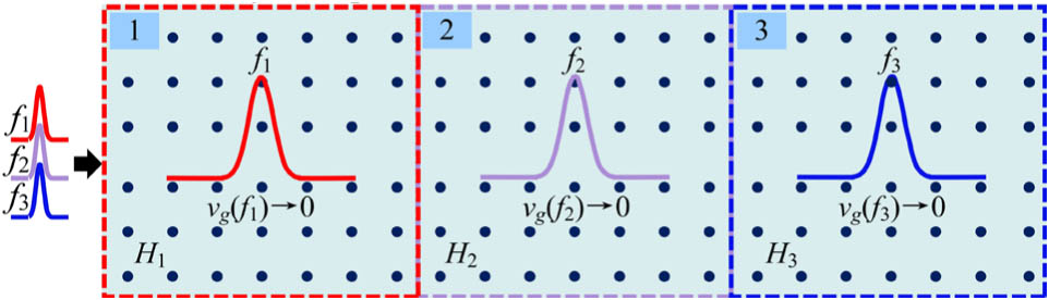
Figure 1.Schematic diagram of SLRT in the MOPC waveguide.
As the basis of our SLRT system, we construct a waveguide by bringing close together face-to-face two identical MOPCs consisting of a square lattice of yttrium-ion-garnet (YIG) rods with permittivity embedded in air, as shown in Fig. 2(a). The width of the waveguide is defined as the distance between the centers of the first row of rods on both sides of the waveguide. When the waveguide width is ( is the lattice constant), it is just a perfect MOPC, and thus it does not support any guided modes. Here, the width is chosen as . The magnetic field is applied along the direction, and the permeability of YIG rods becomes a tensor as follows [26–29]: where , and . Here, is the resonance frequency, is the gyromagnetic ratio, is the characteristic circular frequency with being the saturation magnetization, and is the damping coefficient.

Figure 2.(a) Schematics of the MOPC waveguide involving strongly coupling TPSs. RTPS and LTPS indicate whether the TPSs are propagating rightwards or leftwards, respectively. (b) Band structure of the MOPC waveguide. (c)–(e) Electric field profiles at different frequencies: (c) , (d) , (e) . The area marked by the blue dashed box in (c) is the supercell used in the calculation of the photonic band.
We perform numerical simulations for the MOPC waveguide with . We calculate its band structure, as well as the Chern numbers of each MOPC and air. The results displayed in Fig. 2(b) show that the Chern numbers of two MOPCs are the same (i.e., ), so there exist two isolated counter propagating TPSs, i.e., the left propagating state (LTPS) and right propagating state (RTPS) localized at the upper and lower edge of the waveguide channel, respectively. The strong coupling between LTPS and RTPS induces a close-loop transport of energy flux in the waveguide channel, as depicted by the dashed arrows in Fig. 2(a). Consequently, an unexpected exotic flat band arises in the middle part of Brillouin zone , as shown in Fig. 2(b). As is well known, the group velocity of a guided mode is given by the slope of the tangent line at a given point of the dispersion curve. Therefore, the guided modes belonging to the flat band are extremely slow light states.
Simulations are carried out in an air/MOPC-waveguide/air structure with to demonstrate the harvesting and trapping phenomena, as shown in Figs. 2(c)–2(e). The length of the waveguide is (between and ), being the same as the sizes of regions 1, 2, and 3 in Fig. 1. Three continuous EM waves oscillating at 4.25, 4.292, and 4.35 GHz (corresponding to , , and ) are incident from the left port to propagate along the direction [see Figs. 2(c)–2(e)]. Since drops into the bandgap and is below the flat band, the radiation at is suppressed in the waveguide channel, causing all EM waves at to be completely reflected back into air [see Fig. 2(c)], and none of the energy can pass through the waveguide. In contrast, as is rightly located at the flat band, the energy flux is well confined and enhanced in the waveguide region between and due to the strong mutual coupling of the RTPS and LTPS [see Fig. 2(d)]. This coupling effect results in an extremely slow group velocity of the EM wave and only an extremely small part of energy is reflected to leak into air. Finally, according to Fig. 2(b), the EM wave at has a relatively large group velocity, and thus it can pass through the waveguide fleetly and radiate into the right air region [see Fig. 2(e)]. Thus, no EM wave at can be captured by the waveguide.
3. SWITCHABLE SLOW LIGHT RAINBOW TRAPPING
We display the synthetic diagram of the slow light flat bands at different in Fig. 3(a). As increases, the flat band shifts to a higher frequency region, but their shapes change scarcely, especially in the area of . This diagram clearly reveals that the extremely slow light states can be magnetically tuned within a broad frequency range (3.60–4.48 GHz, near 22% bandwidth). Besides, the EM wave fixed at a specific frequency can be regulated continuously among different cases, including the forbidden state, slow light trapped state, and releasing state with a large group velocity. We choose five flat bands with continuously and linearly increasing from 1600 to 2000 G and calculate the group velocities, respectively. The results are displayed in Fig. 3(b). We select three frequencies of , , and depicted by three dotted lines to demonstrate SLRT. The dashed boxes and dots signs in Fig. 3(b) mark the slow light states and transport states, respectively. In the first case, where is excited, we get and . For the second case, where is excited, we get , , and . For the last case, where is excited, we get , , , and . These interesting properties offer a powerful method for the realization of SLRT.
Figure 3.(a) Flat band with different in the half-Brillouin zone. (b) Group velocities of different flat bands. (c) Electric field profiles at three frequencies: , , and . (d) Electric field amplitudes along the upper boundary as shown in (c).
To demonstrate SLRT, we construct a line defect waveguide channel with each segment size of and exert a special gradient external magnetic field with . A wave packet consisting of , and is incident from the left port. The energies of the three frequency components are trapped in corresponding locations of extremely slow light, as shown in Fig. 3(c), which agrees well with the theoretical prediction. Figure 3(d) shows the normalized amplitudes of the electric field along the upper boundary of the channel, as shown in Fig. 3(c). The amplitudes before each slow light area are extremely small, they become very strong within the slow light area, and they are zero after the slow light area. These phenomena clearly demonstrate that the EM waves at slow light frequencies are harvested efficiently, trapped firmly, and enhanced significantly in the corresponding slow light regions. Besides, for this open waveguide, i.e., a segment with length of , which is about 3.5 times the vacuum wavelength of light, it is long enough to efficiently trap the EM wave inside it to avoid energy crosstalk, leading to a promising fine level of spatial resolution for the SLRT waveguide. Furthermore, the storage lifetime is used to characterize the storage performance. is proportional to the quality factor , and it can be calculated from the electric and magnetic field distributions in the eigenmode field, where is the stored energy, and is the dissipated power. We get , , and . Thus, , 8168, 7980 ( is the oscillation period of light) for , 1800, and 1900 G, respectively, which is quite a long time since the length of the open waveguide is only about 3.5 times the vacuum wavelength of light.
After implementation of harvesting and trapping light in the open waveguide, another question arises: how to release this stored light? As discussed above, the group velocity of light at a single frequency can be changed arbitrarily by tuning . Thus, an easy and efficient way is to appropriately reduce the local magnetic field strength in the gradient magnetic field profile. By this way, the slow light state can be transferred to a transport state with a much larger group velocity to escape from the trapped position in the waveguide. We demonstrate such a switchable operation in Fig. 4. By comparing Fig. 4(a) with Fig. 3(c), in region 2 is reduced from 1700 G to 1650 G, which causes the flat band to move downwards. As a result, locates above the flat band, and its corresponding velocity becomes much larger. Finally the trapped energy pours out of the waveguide from the left port. By similar analyses, we can explain the other two cases in Figs. 4(b) and 4(c). By setting (or 1850 G) in region 3 (or 4), the trapped state at (or ) becomes a transport state, and then the energy of the transport state passes through the left regions to leak out from the left port.
Figure 4.Electric field distributions with a local designed gradient magnetic field. (a) , (b) , (c) .
It should be noticed that the magnetic field intensity in region 3 (or 4) should not be lower than that in region 2 (or 3), in order not to destruct the distributions of trapping energy in the other two regions. Additionally, by finely controlling the gradient magnetic field distribution, we can move, spread, or concentrate the trapped energy in each region of the waveguide conveniently. Meanwhile, the crosstalk and overlapping of energy between neighbor regions are very small. Such unique features surely can greatly improve the spatial resolution and maneuverability of SLRT.
The final thing is to explore the potential capacity of the SLRT bandwidth and spatial length. It should be emphasized that although the operation bandwidth is from 3.6 to 4.48 GHz (about 22% of bandwidth), it is impossible to implement SLRT with such a broad frequency range at the actual design. This is because all of the slow light states should share a common bandgap of MOPC. In fact, the maximum bandgap of the MOPC under different is only 1/4 of the operation bandwidth. For example, when the EM wave at 4.43 GHz (i.e., the slow light frequency for region 5 under ) is incident from the left port, it will excite the bulk states of region 1, leading to the dissipation of energy into the upper and lower bulky MOPCs. As a result, almost no energy is able to reach regions 2 to 5 step by step, and no continuous SLRT distribution can be formed finally. Thus, the maximum available bandwidth to achieve the continuous distribution of SLRT is about 0.212 GHz (from 4.229 to 4.441 GHz). However, this bandwidth is sufficiently broad to construct a large-length broadband SLRT waveguide.
Figure 5 shows the illustration diagram of the large-length SLRT. Each region has a length of so that the overall length of the waveguide is , where represents the number of SLRT components. A wave packet containing frequency components () transports into the waveguide composed of regions () with different magnetic field strengths (), respectively. According to the above discussions, EM waves at will be trapped in regions , respectively, to form an SLRT distribution along the waveguide. Therefore, the incident wave packets are greatly elongated in space. In some sense, the SLRT can be harnessed to serve as an excellent dispersion device for significantly broadening the EM wave packet.
Figure 5.Illustration of broadband large-length SLRT in the MOPC waveguide with a gradient magnetic field.
A Gaussian wave packet centered at is incident from the left port, and the full width at half-maxima of the pulse is . Figures 6(a)–6(d) show the electric field distributions along the upper boundary of the waveguide channel at different times (i.e., 10, 40, 70, and 100 ns). It is noticed that after the wave packet propagates into the waveguide, different frequency components of EM waves can be trapped in different regions for a relatively long time. At , most of the energy arrives in regions 1 and 2, while only a little energy reaches region 3. At , the pulse has gone through the whole structure; however, there still exists a relatively strong electric field distribution inside each region. As time elapses, at , the localized energy in regions 1, 2, and 3 becomes a little weaker due to the leakage of energy on both sides of the waveguide channel. After a long time, at , the phenomenon is similar to the case of , the electric fields in the waveguide channel are still well trapped in each region with only a little dissipation. It should be noticed that there exist reflections at boundaries between the different magnetic domains to cause some distortion of the pulse. We further study its spectrum characteristics. Figure 6(e) presents the normalized spectrum obtained by Fourier transformation at , , , and . The corresponding peak frequencies are at , , and , respectively, which exhibit a blue-shift as for each region increases, and they agree well with our frequency domain simulations (, , and ). These results provide a very informative picture to demonstrate slow light and pulse trapping.
Figure 6.Electric field amplitudes of the wave packet along the upper boundary at different times: (a) 10 ns, (b) 40 ns, (c) 70 ns, and (d) 100 ns. The magnetic field strengths applied to the regions 1, 2, and 3 are , , and , respectively. (e) Fourier transformation spectrum normalized to each amplitude at , , , and along the upper boundary of the waveguide. (f) The partial enlargement of the area marked by the black dashed box in (e).
4. CONCLUSIONS
In conclusion, we have presented a scheme to realize a novel switchable SLRT state by exploring the MOPC waveguide channel exerted with an adjustable gradient magnetic field. The SLRT waveguide exhibits several unique features: it supports slow light states with extremely small group velocity (), low group-velocity dispersion, and a broadband operation bandwidth (3.60–4.48 GHz, near 22% of bandwidth). Under a gradient magnetic field, an input broadband wave packet will have its different frequency components separated and stored at different positions to form SLRT. Moreover, these SLRT states are easily switched among the forbidden state, trapped state, and releasing state by simply tuning the gradient magnetic field. This unique switchable SLRT system exhibits a series of advantageous merits of high spatial resolution, broad frequency range, long stored lifetime, multipurpose operation, and low crosstalk. The design of such a device will provide a novel, insightful, and practically feasible method for optical buffers, broadband slow light systems, optical filters, wavelength-division multiplexing, and other optical communication devices. The underlying physical insights will expand our understanding of the peculiar properties of TPSs by exploring their mutual interactions and open up a new avenue to control the space–time field evolution, energy flux flow, and EM wave transport of light for exploring novel applications in information technology.
References
[1] Z. Dutton, M. Budde, C. Slowe, L. V. Hau. Observation of quantum shock waves created with ultra-compressed slow light pulses in a Bose–Einstein condensate. Science, 293, 663-668(2001).
[2] F. Grusdt, M. Fleischhauer. Tunable polarons of slow-light polaritons in a two-dimensional Bose–Einstein condensate. Phys. Rev. Lett., 116, 053602(2016).
[3] M. J. Akram, F. Ghafoor, M. M. Khan, F. Saif. Control of Fano resonances and slow light using Bose–Einstein condensates in a nanocavity. Phys. Rev. A, 95, 023810(2017).
[4] M. G. Herráez. Arbitrary-bandwidth Brillouin slow light in optical fibers. Opt. Express, 14, 1395-1400(2006).
[5] W. Qiu, J. Liu, Y. Wang, Y. Yang, Y. Gao, P. Lv, Q. Jiang. Demonstration of slow light propagation in an optical fiber under dual pump light with co-propagation and counter-propagation. Opt. Commun., 413, 207-211(2018).
[6] Q. Gan, Z. Fu, Y. J. Ding, F. J. Bartoli. Ultrawide-bandwidth slow-light system based on THz plasmonic graded metallic grating structures. Phys. Rev. Lett., 100, 256803(2008).
[7] J. M. Shainline, J. Xu. Slow light and band gaps in metallodielectric cylinder arrays. Opt. Express, 17, 8879-8891(2009).
[8] T. Baba. Slow light in photonic crystals. Nat. Photonics, 2, 465-473(2008).
[9] S. A. Schulz, J. Upham, L. O. Faolain, R. W. Boyd. Photonic crystal slow light waveguides in a kagome lattice. Opt. Lett., 42, 3243-3246(2017).
[10] K. L. Tsakmakidis, O. Hess. Slow and stopped light in metamaterials, the trapped rainbow. Proc. SPIE, 6987, 698702(2008).
[11] Y. Shen, J. Fu, G. Yu. Rainbow trapping in one-dimensional chirped photonic crystals composed of alternating dielectric slabs. Phys. Lett. A, 375, 3801-3803(2011).
[12] H. Kurt, D. Yilmaz. Rainbow trapping using chirped all-dielectric periodic structures. Appl. Phys. B, 110, 411-417(2013).
[13] H. Zhou, T. Gu, J. F. Mcmillan, M. Yu, G. Lo, D. L. Kwong, G. Feng, S. Zhou, C. W. Wong. Enhanced photoresponsivity in graphene-silicon slow-light photonic crystal waveguides. Appl. Phys. Lett., 108, 111106(2016).
[14] Z. Hayran, H. Kurt, K. Staliunas. Rainbow trapping in a chirped three-dimensional photonic crystal. Sci. Rep., 7, 3046(2017).
[15] Z. Tian, L. Yu. Rainbow trapping of ultrasonic guided waves in chirped phononic crystal plates. Sci. Rep., 7, 40004(2017).
[16] W. Xue, Y. Yu, L. Ottaviano, Y. Chen, E. Semenova, K. Yvind, J. Mork. Threshold characteristics of slow-light photonic crystal lasers. Phys. Rev. Lett., 116, 063901(2016).
[17] Q. Gan, Y. J. Ding, F. J. Bartoli. Rainbow trapping and releasing at telecommunication wavelengths. Phys. Rev. Lett., 102, 056801(2009).
[18] H. Hu, D. Ji, X. Zeng, K. Liu, Q. Gan. Rainbow trapping in hyperbolic metamaterial waveguide. Sci. Rep., 3, 1249(2013).
[19] M. Hussein, M. F. O. Hameed, N. F. F. Areed, A. Yahia, S. S. A. Obayya. Funnel-shaped silicon nanowire for highly efficient light trapping. Opt. Lett., 41, 1010-1013(2016).
[20] L. Chen, G. P. Wang, Q. Gan, F. J. Bartoli. Rainbow trapping and releasing by chirped plasmonic waveguides at visible frequencies. Appl. Phys. Lett., 97, 153115(2010).
[21] M. S. Jang, H. Atwater. Plasmonic rainbow trapping structures for light localization and spectrum splitting. Phys. Rev. Lett., 107, 207401(2011).
[22] B. Guo, W. Shi, J. Yao. Slowing and trapping THz waves system based on plasmonic graded period grating. J. Opt., 45, 50-57(2016).
[23] R. J. P. Engelen, D. Mori, T. Baba, L. Kuipers. Two regimes of slow-light losses revealed by adiabatic reduction of group velocity. Phys. Rev. Lett., 101, 103901(2008).
[24] J. He, Y. Jin, Z. Hong, S. He. Slow light in a dielectric waveguide with negative-refractive-index photonic crystal cladding. Opt. Express, 16, 11077-11082(2008).
[25] Y. Liu, Y. Wang, G. Han, Y. Shao, C. Fang, S. Zhang, Y. Huang, J. Zhang, Y. Hao. Engineering rainbow trapping and releasing in ultrathin THz plasmonic graded metallic grating strip with thermo-optic material. Opt. Express, 25, 1278-1287(2017).
[26] Y. Yang, Y. Poo, R. X. Wu, Y. Gu, P. Chen. Experimental demonstration of one-way slow wave in waveguide involving gyromagnetic photonic crystals. Appl. Phys. Lett., 102, 231113(2013).
[27] J. Chen, W. Liang, Z. Y. Li. Strong coupling of topological edge states enabling group-dispersionless slow light in magneto-optical photonic crystals. Phys. Rev. B, 99, 014103(2019).
[28] Z. Wang, Y. D. Chong, J. D. Joannopoulos, M. Soljačić. Reflection-free one-way edge modes in a gyromagnetic photonic crystal. Phys. Rev. Lett., 100, 013905(2008).
[29] Z. Wang, Y. Chong, J. D. Joannopoulos, M. Soljačić. Observation of unidirectional backscattering-immune topological electromganetic states. Nature, 461, 772-775(2009).

