Abstract
We demonstrate a diode-pump -doped all-fiber laser operating at 1908 nm based on a master oscillator power amplifier (MOPA) configuration. In our work, 152 W of laser output power is generated by a total incident pump power of 434 W at 790 nm, corresponding to the total optical efficiency of 35%. The laser wavelength is 1908.29 nm. To the best of our knowledge, it is the highest output power reached around 1908 nm with such a narrow linewidth of 0.18 nm based on a MOPA configuration.Lasers operating at the 2 μm eye-safe waveband are attracting significant interest in both research and industrial applications, such as sensing, spectroscopy, material processing applications, and nonlinear frequency conversion[1–3]. The 2 μm waveband has rich absorption lines of various molecules, such as , , , and [4], which can be employed in many areas. For instance, as the first overtone vibration of at 1.9 μm falls in this region[5], a laser source matching this absorption wavelength would be very useful for atmospheric LIDAR sensing[6,7] as well as medical and surgical applications[8,9]. Lasers at 1908 and 1940 nm are an important branch of lasers at the 1.9 μm waveband. Lasers at 1908 nm can generate lasers at 2.09 μm by pumping a Ho:YAG crystal[10]. Lasers at 1940 nm can generate lasers at 2.05 μm by pumping a Ho:YLF crystal[11]. Then, the lasers at 2.09 and 2.05 μm can generate lasers at 3–5 and 8–12 μm by pumping a ZGP crystal. Lasers at 3–5 and 8–12 μm were widely applied in optoelectronic countermeasures and LIDAR systems, which needed high-power and narrow spectral linewidths to achieve long-distance interference and sensing. So increasing the pumping power was a significant way to achieve these purposes. Usually, we obtain lasers at 1908 nm in one of two ways: by using solid-state lasers or fiber lasers. The Tm:YLF laser is one of the best choices for the solid-state laser to generate this waveband laser with higher efficiency. However, the losses and thermal effects can lead the solid-state laser to show a lower optical efficiency and worse beam quality factor of [12]. All-fiber lasers have lower losses and thermal effects due to the waveguide configuration, which means they have a higher optical efficiency, output power, and better beam quality factor of . In addition, all-fiber lasers have many advantages, such as a compact structure, lightness in weight, simple operation, and good beam quality[13–15]. With the development of high-power laser diode (LD) technology, the output power of the 1908 nm wavelength fiber laser has increased substantially. The -doped fiber (TDF) is the main gain medium to generate the 1908 nm wavelength laser. However, thulium is a quasi-three-level system that suffers from strong reabsorption loss below 1.95 μm at room temperature[16], so it is difficult to generate high output power in this waveband. Using a 350 W 788 nm LD as the pumping source, Shayne Bennetts et al. achieved a 110 W laser at 1908 nm in a TDF laser with a resolution-limited linewidth of 0.5 nm in 2008. They used a fiber Bragg grating (FBG) and a polished fiber end facet as cavity mirrors[17]. With the development of pump coupling technology, Hu et al. used a combiner to obtain up to 227 W of 1908 nm laser output power with 490 W of 793 nm pump power in 2014[18]. That is the highest output power achieved operating at 1908 nm up to now. The linewidth of the output laser was not given exactly in their Letter. It looked as it was about 7 nm due to the illustration in that Letter. The laser’s broad linewidth made it difficult to pump the Ho:YAG crystal efficiently. The feedback could get into the LDs due to the configuration of using a combiner and destroy the pumping source when the power was high enough. In addition, it was too high for FBGs to endure over 200 W of power. Generally speaking, the master oscillator power amplifier (MOPA) configuration is a better way to solve the problem. Frith et al. achieved a 70 W 1908 nm laser using an MOPA configuration in 2008. The TDF used in the master oscillator (MO) stage had a mode field diameter of 10.2 μm. The TDFs absorption coefficient was 2 dB/m at 790 nm. Two FBGs were used as cavity mirrors. An end-pumped configuration was used to pump the TDF with a fiber-coupled 795 nm LD. The MO stage can produce a 10 W laser at 1908 nm. The active fiber used in the power amplifier (PA) stage had a mode field diameter of around 22 μm. The absorption coefficient of the active fiber was 6 dB/m at 790 nm. Two LDs were used as the pump sources. Each one could deliver up to 65 W of pump power into the laser cavity via a pump combiner by the counter-pumping mode[19]. However, the pumping source of the MO stage was easily impacted by the feedback, which may ruin the pumping sources in the MO stage when the power is high enough.
In this Letter, we demonstrated a -doped double-clad all-fiber laser. We improved the form of the incident pump power in the MO stage via a combiner to avoid the influence of the feedback on the pumping sources and obtained 152 W of output power at 1908 nm by the MOPA configuration, corresponding to a total optical efficiency of 35%. To the best of our knowledge, it is the highest output power for an all-fiber laser operating at 1908 nm by an MOPA configuration with the narrow linewidth of 0.18 nm up to now.
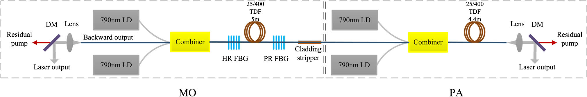
To achieve high power and a stable laser output, the MOPA configuration was employed in our experiment, as shown in Fig. 1. Four 790 nm LDs were used to provide the pump power for the laser cavity by the forward-pumping mode. Two LDs were used in the MO stage and the others were in the PA stage. The combiner was used to couple the pump power into the laser cavity. Both the forward-pumping mode and the combiner were used to reduce the influence on the LDs due to the feedback. The free-fiber end facets were cleaved an angle of 8° to prevent unwanted feedback from the Fresnel reflection. The cladding stripper between two stages was used to eliminate the interferences. The large mode area TDF was designed for operations at shorter wavelengths to provide sufficient gain. The active fibers in the MO and PA stages were placed into a 180 mm diameter bronze plate with a helically cut “U-shaped” channel for effective heat removal. Since the splices between two kinds of fibers were the most unsubstantial places except for the TDF, all splices were put straight into a bronze heat sink for efficient thermal dissipation.
Sign up for Chinese Optics Letters TOC. Get the latest issue of Chinese Optics Letters delivered right to you!Sign up now

Figure 1.Schematic of MOPA laser system.
The MO stage was used to provide the seed laser for the PA stage. The active fiber employed in the MO stage was the TDF (Fiberhome Co. China) with a core diameter of 25 μm and a 0.09 NA. The absorption coefficient was 1.67 dB/m at 790 nm. The pure silica inner cladding, coated with a low-index polymer, had a 400 μm diameter and a 0.46 NA. The low absorption ensured low heat produced by the energy transfer upconversion and rapid non-radiative transition at the unit length on the TDF. The large inner cladding diameter ensured that enough pump energy was stored in the fiber. A 5 m-long active fiber was designed into the MO stage to provide sufficient gain. The pump sources were two 790 nm high-power LDs with 200 μm core/220 μm cladding diameter fiber pigtails and 0.22 NA. The fiber pigtails were the same size as the pump fiber pigtails of the fiber combiner. The two LDs could generate up to 220 W of pump power. A high-power fiber combiner (LIGHTCOMM Co., China) was used to couple the pump power into the laser cavity. The signal fiber of the fiber combiner was a double-clad passive fiber. It had a 25 μm core diameter (0.09 NA) and a 400 μm inner cladding diameter (0.46 NA). The pump fiber was a single-clad passive fiber. It had a 200 μm core diameter (0.22 NA) and a 220 μm cladding diameter. The coupled efficiency of the fiber combiner was 93%. A pair of specially designed chirped FBGs (ITF Co., Canada) was used to complete the laser cavity with the active fiber. Also, the signal laser wavelength was selected by the FBGs. One of the FBGs was highly reflective (HR, ) with a central wavelength of 1908.06 nm, and the other was partially reflective (PR, ) with a central wavelength of 1907.72 nm. The HR grating had a wider spectral FWHM of 2.37 nm, and the PR grating had a spectral FWHM of 1.00 nm at room temperature. The seed laser generated in the MO stage was delivered into the PA stage for power scaling. Considering that the PA stage needed a seed laser with good beam quality from the MO stage, a cladding stripper that can remove higher-order modes generated between the MO and PA stages was carefully designed on the passive fiber. Meanwhile, the cladding stripper also served to remove residual unabsorbed pumps in cladding from the two stages so as to avoid interference. A 1.5 m-long passive fiber was used to make the cladding stripper. The passive fiber has the same size and NA as the active fiber so as to match the mode field. In the middle part of the fiber, an about 8 cm-long fiber was peeled off the coating and steeped in a saturated solution for 40 min. Then, the part fiber was taken out and cleaned by ultrasonic cleaner. Considering the large amount of heat when the stripper was working, it was packaged in a black aluminum box for easy moving and cooling. The inner cladding light is removed with the cladding stripper because the inner cladding surface becomes rough and the light diffuses and spills over the fiber.
The PA stage was used to amplify the seed laser from the MO stage. The pump power was up to 240 W and launched by two LDs. The fiber pigtails of the LDs were spliced to the pump fiber pigtails of the combiner. Another input signal fiber was spliced to the output fiber of the MO stage. About 229.4 W of pump power was finally obtained from the combiner. A 4.4 m-long TDF was carefully spliced to the output end of the combiner to provide sufficient gain for power scaling. Considering the pump absorption by the active fiber, paying careful attention to the thermal management was essential for maintaining reliability and efficiency. The influence of the optical efficiency with respect to the fiber temperature for the 790 nm pumping TDF was reported in the past[20]. A bronze plate with a helically cut “U-shaped” channel was used to ensure highly effective heat removal. The smaller diameter of the bronze plate provided sufficient mode control to obtain good beam quality. The passive fiber was spliced to the active fiber so as to lead the laser out. The splices at the two ends of the active fiber were straightened and pressed in the “U-shaped” channel of the bronze plate.
In the MO stage, under the maximum pump power of 204 W from the combiner, 74 W of laser output power at 1908 nm was obtained by utilizing a dichroic mirror (DM) ( at 1.9 μm, 45°). The slope efficiency was 42.5%, and the optical efficiency was 36.3%. To eliminate the residual pump light and signal laser in the inner cladding of the MO, a cladding stripper was designed at the fiber output end. With the cladding stripper, the output power was measured again. Under the maximum pump power, 68 W of output power was obtained. The slope efficiency was 40.4%, and the optical efficiency was 33.3%, as shown in Fig. 2.
Figure 2.Output laser slope efficiency of the MO.
This implies that 6 W of laser power got into the inner cladding. If the laser power was not eliminated by the cladding stripper, it would transmit in the fiber inner cladding, and the output characteristics of the laser beam would be seriously affected.
In the PA stage, the signal fiber of the combiner was directly spliced to the fiber pigtail of cladding stripper of the MO stage. The fibers are the same as the passive fiber, so there is no additional loss except for splice loss. We separately measured the slope efficiencies at the seed laser powers of 9.7, 27.5, 45.7, 59.0, and 67.8 W, as shown in Fig. 3. When the seed laser output powers at 9.7, 27.5, and 45.7 W, the slope efficiency was increased. When the seed laser power exceeded 45.7 W, the slope efficiency was increased indistinctively. With the 67.8 W seed laser power and 229.2 W of delivered pump power in the PA stage, 152 W of laser power was obtained by a DM ( at 1.9 μm, 45°), corresponding to the slope efficiency of 45.3%. The saturation effect observed in the PA stage was not obvious.
Figure 3.Laser output power and slope efficiency in the PA with different seed laser powers.
The 10%–90% knife-edge method was used to measure the relationship between the beam radius and the beam position around the focus. The focal spot radius, focal position, and confocal parameter were obtained by the Gaussian-fit method. The beam quality factor of was 2.1 and calculated by the parameters, as shown in Fig. 4. As the cladding stripper could not afford such a high power of 150 W, we did not splice a cladding stripper at the output end of the PA stage. That might be the main reason why the laser output beam quality was not good. The laser wavelength was 1908.29 nm at the laser power of 150 W, corresponding to the linewidth of 0.18 nm, as shown in Fig. 5. The inset of Fig. 5 is the power spectrum of the log intensity from 1880 to 2000 nm.
Figure 4.Beam quality factor of at 150 W.
Figure 5.Central wavelength and linewidth at 150 W. The inset is the power spectrum of the log intensity.
In addition, the laser wavelength could be tuned because the central reflective wavelength of the FBG was sensitive to the temperature and the strain. Based on the FBG’s reflective wavelength function, , where is the central reflective wavelength of the FBG, is the core effective refractive index of the FBG, and is the grating pitch of the FBG. The temperature variation could cause the relative refractive index to change. The strain variation could cause the grating pitch to change. Correspondingly, the operation of raising the FBG temperature or pulling the FBG would lead to a red shift. On the contrary, the operation would lead to a blue shift. It was absolutely dangerous to applying a strain to the FBG at the very high laser power of 150 W. So it was a feasible way to tune the laser wavelength via changing the FBG temperature. Since the FWHM of the HR FBG was wider than that of the PR FBG, it was more sensitive to the temperature changes of the PR FBG. The laser central wavelength tuned by the temperature variation of the PR FBG was about 0.02 nm/°C, according to the measurements.
In conclusion, we demonstrate a high-power TDF laser with an MOPA configuration with a narrow spectral linewidth of 0.18 nm. Up to a 152 W laser operating at 1908 nm is obtained with the total incident pump power of 434 W. To the best of our knowledge, 152 W is the highest output power obtained operating at 1908 nm by an all-fiber MOPA configuration with a linewidth of 0.18 nm up to now. The slope efficiency is 42.5% in the MO stage and 45.3% in the PA stage, corresponding to a total optical efficiency of 35%. The central wavelength of the fiber laser is 1908.29 nm at 150 W, corresponding to the linewidth of 0.18 nm. In order to remove residual pump light and signal light that leaked into fiber’s inner cladding, a cladding stripper is used between the two stages. The beam quality factor of is 2.1. The all-fiber laser with the MOPA configuration shows good stability and repeatability in the experiments, and no output power roll-over phenomenon is observed. Thus, this suggests that the laser output power can be further scaled up by more pump power being launched into the amplifier. Additionally, changing the temperature or strain to the PR FBG may realize a tunable output wavelength.
References
[1] A. Hemming, J. Richards, A. Davidson, N. Carmody, S. Bennetts, N. Simakov, J. Haub. Opt. Express, 21, 10062(2013).
[2] R. A. Hayward, W. A. Clarkson, P. W. Turner, J. Nilsson, A. B. Grudinin, D. C. Hanna. Electron. Lett., 36, 711(2000).
[3] S. M. Azooz, F. Ahmad, H. Ahmad, S. W. Harun, B. A. Hamida, S. Khan, A. Halder, M. C. Paul, M. Pal, S. K. Bhadra. Chin. Opt. Lett., 13, 030602(2015).
[4] R. M. Mihalcea, M. E. Webber, D. S. Baer, R. K. Hanson, G. S. Feller, W. B. Chapman. Appl. Phys. B, 67, 283(1998).
[5] G. M. Hale, M. R. Querry. Appl. Opt., 12, 555(1973).
[6] S. W. Henderson, C. P. Hale, J. R. Magee, M. J. Kavaya, A. V. Huffaker. Opt. Lett., 16, 773(1991).
[7] T. Y. Dai, Y. L. Ju, X. M. Duan, W. Liu, B. Q. Yao, Y. Z. Wang. Appl. Phys. B, 111, 89(2013).
[8] R. L. Blackmon, J. Case, P. B. Irby, S. R. Trammell, N. M. Fried. J. Biomed. Opt., 18, 028001(2013).
[9] S. Wenk, S. Furst, V. Danicke, D. T. Kunde. Adv. Med. Eng., 114, 447(2007).
[10] E. Ji, Q. Liu, Z. Hu, P. Yan, M. Gong. Chin. Opt. Lett., 13, 121402(2015).
[11] C. Yang, Y. L. Ju, B. Q. Yao, T. Y. Dai, X. M. Duan, J. Li, Y. Ding, W. Liu, Y. B. Pan, C. Y. Li. Opt. Laser Technol., 77, 55(2016).
[12] Y. J. Shen, B. Q. Yao, C. P. Qian, X. M. Duan, T. Y. Dai, Y. Z. Wang. Appl. Phys. B, 118, 555(2015).
[13] Y. L. Tang, C. Y. Huang, S. L. Wang, H. Q. Li, J. Q. Xu. Opt. Express, 20, 17539(2012).
[14] W. Dai, Y. Song, B. Xu, A. Martinez, S. Yamashita, M. Hu, C. Wang. Chin. Opt. Lett., 12, 111402(2014).
[15] G. Galzerano, E. Sani, A. Toncelli, G. D. Valle. Opt. Lett., 29, 715(2004).
[16] G. Frith, A. Carter, B. Samson, G. Town. Appl. Opt., 48, 5072(2009).
[17] S. Bennetts, A. Hemming, A. Davidson, D. G. Lancaster. OECC/ACOFT 2008, 327(2008).
[18] Z. Y. Hu, P. Yan, Q. R. Xiao, Q. Liu, M. L. Gong. Chin. Phys. B, 23, 104206(2014).
[19] G. Frith, A. Carter, B. Samson, J. Farroni, K. Farley, K. Tankala. Opto-Electronics and Communications Conference(2008).
[20] G. Frith, D. G. Lancaster, S. D. Jackson. Proc. SPIE, 5620, 36(2004).