Laboratory of Nanophotonic Functional Materials and Devices, School for Information and Optoelectronic Science and Engineering, South China Normal University, Guangzhou 510006, China
Ruitong Zhao, Ruisheng Liang. Quantum information transfer between photonic and quantum-dot spin qubits[J]. Chinese Optics Letters, 2016, 14(6): 062701
Copy Citation Text
We propose schemes for the efficient information transfer between a propagating photon and a quantum-dot (QD) spin qubit in an optical microcavity that have no auxiliary particles required. With these methods, the information transfer between two photons or two QD spins can also be achieved. All of our proposals can work with high fidelity, even with a high leakage rate. What is more, each information transfer process above can also be seen as a controlled-NOT (CNOT) operation. It is found that the information transfer can be equivalent to a CNOT gate. These proposals will promote more efficient quantum information networks and quantum computation.
The faithful transfer of quantum information and logical operation between a propagating photon and a stationary qubit plays a significant role in quantum information science such as quantum networks[1], quantum repeaters[2], and optics quantum computing[3,4], since photons are the perfect candidates for fast and reliable long-distance communication, while stationary qubits are suitable for processor and local storage. Some schemes for the interaction between photonic and stationary qubits, for example atomic qubits[5,6], have been reported. In recent years, semiconductor quantum dots (QDs) have attracted extensive attention. As romising solid-state qubits, single spin confined in QD has a long coherence time[7,8] and a potential for integration on a chip[9,10]. Moreover, QD manipulation has had significant progress[11–13]. Many quantum communication and quantum computation schemes have been proposed based on QD spins combined with optical microcavities such as entanglement measurements[14,15], quantum logic gates[16–19], entanglement generators[20], and quantum repeaters[21]. In 2013, Gao et al. experimentally demonstrated the transfer of quantum information carried by a photonic qubit to a QD spin qubit using quantum teleportation[22]. They generated an entangled spin-photon state in a QD and interfered the photon with a single photon in a superposition state of two colors, i.e., a photonic qubit in a Hong–Ou–Mandel setup. A coincidence detection at the output of the interferometer heralds a successful teleportation. The demonstration of successful quantum teleportation of photonic and QD spin qubits could promote the realization of on-chip quantum networks based on semiconductor nanostructures.
The interaction between a circularly polarized beam of light and a QD-cavity system is introduced first. Then, we propose information transfer between a photon and a QD spin in an optical microcavity, with no auxiliary particle required. The information transfer between two photons or two QD spins is proposed with a QD spin or a photon as auxiliary photon. All of the information transfer processes above can be achieved deterministically and can be seen as controlled-NOT (CNOT) gates for quantum computation.
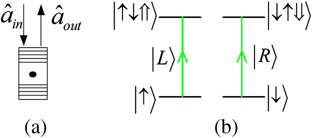
Considering a singly charged QD in an optical microcavity shown in Fig. 1, if the injected excess electron spin is in the state , the QD-cavity system resonantly absorbs a left-handed circularly polarized beam of light and creates a negatively charged exciton in the state . If the injected excess electron spin is in the state , the QD-cavity system resonantly absorbs a right-handed circularly polarized beam of light and creates a negatively charged exciton in the state . Here, and represent the heavy-hole spin states and , respectively. Due to this spin selection rule, the - and -light encounter different phase shifts after reflection from the cavity system.
Sign up for Chinese Optics Letters TOC. Get the latest issue of Chinese Optics Letters delivered right to you!Sign up now
The Heisenberg equations for the cavity field operator and the QD dipole () operator in the interaction picture, and the input-output equation are given by[23]where , , and are the frequencies of the input probe light, cavity mode, and transition, respectively, is the coupling strength between and the cavity mode, and are the decay rates of and the cavity field, and is the side leakage rate of the cavity.
If the QD couples to the cavity, we call it a hot cavity; if the QD does not couple to the cavity, we call it a cold cavity. In the weak excitation approximation, the reflection coefficient in the steady state for hot cavity can be obtained[24] as follows: If the and the cavity mode are uncoupled (a cold cavity), the coupling strength is and the reflection coefficient is If the single excess electron lies in the spin state , the photon feels a hot cavity and gets a phase shift of after reflection, whereas the photon feels the cold cavity and gets a phase shift of . Conversely, if the electron lies in the spin state , the photon feels a hot cavity and get a phase shift of after reflection, whereas the photon feels the cold cavity and gets a phase shift of . The side leakage can be neglected in ideal conditions. For the hot cavity where strongly couples to the cavity, (,). So when . For the cold cavity, . We can obtain . With the initial states of an electron spin and a circularly polarized photon in states and , after being reflected, the light-spin state evolves as where , , and . is the Faraday rotation angle. When the frequency , the phase-shift difference between the left-hand circular polarization light and the right-hand circular polarization light will be .
Suppose that a photon is in a superposition state (), which is the state transferred to a solid-state qubit. The setup of information transfer from a photon to a solid-state qubit is shown in Fig. 2. The spin state of QDs is generated in . After the photon passing through the half-wave plate (HWP) and phase shift P, the state of the photon is
Figure 1.Spin-dependent transitions for negatively charged exciton . (a) A charged QD inside a micropillar microcavity with circular cross section. (b) The spin selection rule for optical transitions of negatively charged exciton due to the Pauli’s exclusion principle. and represent the left- and the right-hand circularly polarized lights, respectively.
Figure 2.Diagram of information transfer from a photon to a solid-state qubit. HWPs denote half-wave plates that are used to perform Hadamard operations. P denotes a phase shift on the polarization state. PBS denotes a polarization beam splitter that transmits photon and reflects photon. and are single-photon detectors.
Then the photon interacts with the QD. The state of the system of the photon and the QD will be Because of the second HWP, the state will be converted to Then we implement a phase shift on . The state will be It can be seen that, if is clicked, the spin state of the QD will be . Obviously, the information of the photon is transferred to the solid-state QD spin qubit. If is clicked, the spin state of the QD will be , which can be converted to by a single-qubit operation. So the information transfer from a photon to a solid-state QD spin qubit is deterministic.
What’ is more, the setup above implements the transformation as follows: Obviously, it is a CNOT operation with the QD spin as the control qubit and the photon as the target qubit. When the spin state is , the photon state will be inverted. Otherwise, the photon state will remain unchanged.
Next, we consider the inverse case, which is the information transfer from a solid-state qubit to a photon shown in Fig. 3.
Figure 3.Setup of the information transfer from a solid-state qubit to a photon. is used to modulate the spin state of the QD. The modulation of the spin state of the QD will be implemented two times before () and after () the photon passes through the QD.
Suppose that the spin state of the QD is and the state of photon is . Before the interaction between the photon and the QD, an operation in basis vectors as follows is implemented on the spin state of QD utilizing a pulse: Then, the spin state of the QD is . Because of the interaction between the photon and the QD, the state of the whole system is Then, the operation is implemented on the spin state of the QD. The state of the system will be which can be converted to the following state by a phase shift on : After that, a measurement will be implemented on the spin state of QD. If is obtained, the state of the photon will be , which can be converted to by a single-photon operation. Obviously, the information of the solid-state QD spin qubit is transferred to the photon. If is obtained, the state of the photon will be . So the information transfer from the solid-state QD spin qubit to the photon is also deterministic.
Similar to the information transfer from a solid-state qubit to a photon, the process above can be seen as the following transformation: It is a CNOT operation with the photon as control qubit and the QD spin as the target qubit. When the photon state is , the QD spin state will be inverted. Otherwise, the QD spin state will remain unchanged.
With the methods above, we can also achieve the information transfer between QD spins. Now, we explain the principle of information transfer from a QD spin to another QD spin assisted by a photon, which is shown in Fig. 4.
Figure 4.Diagram of the information transfer between QD spins. Obviously, the red block shows the information transfer from a QD-spin qubit to a photon in Fig. 3, and the green block denotes the information transfer from a photon to a QD-spin qubit in Fig. 2.
This process can be divided into two steps. 1. Information transfer from a QD spin to a photon. 2. Information transfer from the photon to another QD spin. We assume that the initial states of the excess electron spin in and are and , respectively. The photon is initially generated in state . So the state of combined system is After the red block, the combined state will be When the photon passes through the green block, the combined state is converted to The excess electron spin in can be in the initial states of the excess electron spin in by a single-qubit operation according to the measurement results of the states of the electron spin in and the photon. If is obtained, the electron spin state in is and no operation is required. If is obtained, we can implement a operation on to achieve the information transfer. For and , the operations needed are and , respectively. This information transfer is also deterministic.
Equation (18) is equivalent to If the photon is in state , the two QDs are in , which is a CNOT gate with as the control qubit and as the target qubit. If is obtained, the two QDs will be , which can be converted to by a operation on . It can be seen that this is also a CNOT gate with as control qubit and as target qubit.
The opposite is also workable. The information transfer between two photons can be achieved by information transfer from a photon to a QD spin and information transfer from a QD spin to another photon.
We assume that the initial states of photons and are and , respectively. The spin state of the QD is . So the system is in the state As shown in Fig. 5, photons and pass through the QD in sequence. After photon passes through the QD and HWPs, the combined state is
Figure 5.Diagram of the information transfer between photons. Photons and pass through the QD in sequence. is also used to modulate the spin state of the QD. The modulation of the spin state of the QD will be implemented two times before () and after () the photon passes through the QD.
Then is implemented two times before () and after () photon passes through the QD. The state will be Photon can be in the initial states of photon by a single-photon operation according to the measurement results of the states of the electron spin in the QD and photon . If is obtained, the state of photon is and no operation is required. If is obtained, we can implement a operation on photon to achieve the information transfer. For and , the operations needed are and , respectively. This information transfer is also deterministic.
Equation (22) is equivalent to If the QD is in state , the two photons are in , which is a CNOT gate with photon as the control qubit and photon as the target qubit. If is obtained, the two photons will be , which can be converted to by a operation on photon . It can be seen that this is also a CNOT gate with photon as the control qubit and photon as the target qubit.
If the cavity side leakage is neglected, the fidelity of the information transfer can reach 100%. However, this is a big challenge for QD cavities with current technology. If we take the cavity side leakage into account, the fidelity can be calculated. Here, is the final state of the total system, which includes the external reservoirs, and is the final state under ideal conditions. The fidelity (in amplitude) of the information transfer from a photon to a QD spin is equal to that from a QD spin to a photon, and the fidelity of the information transfer between two photons or two QD spins is also equal, and can be denoted as and , respectively, where and .
The fidelities are calculated by the square of the modulus of and , so there are deviations and fluctuations in a weak coupling regime. When , and vary sharply versus and . So does and . Otherwise, and reach plateaus versus the coupling strength for a certain leakage rate, which can be seen in Fig. 6. For smaller leakage rates , and for both the weak coupling regime () and the strong coupling regime (). When , the fidelities reduce significantly with increasing leakage rate.
Figure 6.Fidelities of the information transfer schemes versus the coupling strength for different leakage rates . (a) The fidelity of the information transfer from a photon to a QD spin, which is equal to that from a QD spin to a photon. (b) The fidelity of the information transfer between two photons or two QD spins. Here, the four curves correspond to the cases of , 0.2, 0.5, and 1, respectively. We take and .
For a weak coupling regime , and are 99.9251% and 99.85% with , and and are 99.45% and 98.91% with . When , and 87.94%, and and 78.79% with , 1, respectively. The fidelities plateau for certain leakage rate again when . For , and 87.83% and and 78.62% with , 1, respectively. What is more, the minimums of and approach 61% and 52% with . The weak coupling regime of the QD-cavity system can be easily achieved in experiments, and strong coupling in a QD-cavity system has also been reported. The coupling strength can be increased from (for a quality factor )[25] to (for a quality factor )[26] in micropillar microcavities with . From the discussion above, we can see that our proposals work with a high fidelity in both the strong coupling regime and the weak coupling regime even with high leakage rates (). However, the fidelities indeed decrease with increasing leakage rates, so a smaller leakage rate is necessary.
In conclusion, we propose information transfer between a photon and a QD spin in this Letter. The information carried by a photon can be transferred to a QD-spin qubit deterministically with no auxiliary particle required, and vice versa. Furthermore, each information transfer process above can be seen as a CNOT operation with a QD spin or a photon as the control qubit. Then the information transfer between two photons or two QD spins is proposed, which a QD spin or a photon as auxiliary, and these proposals can also be seen as deterministic CNOT gates. All of our proposals work with high fidelity in both the strong coupling and the weak coupling cases, even with high leakage rates. A photon is a propagating qubit used for the transmission of quantum information, and a QD spin is a stationary qubit used for storage and manipulation. So the information transfer between a photon and a QD spin achieves an interface between a propagating qubit and a stationary qubit for quantum information storage and readout, which plays a central role in quantum communication networks. Given the CNOT gates between these particles, these proposals could also be used as quantum computational primitives.
Ruitong Zhao, Ruisheng Liang. Quantum information transfer between photonic and quantum-dot spin qubits[J]. Chinese Optics Letters, 2016, 14(6): 062701