State Key Laboratory of Precision Measurement Technology and Instruments, Department of Precision Instruments, Tsinghua University, Beijing 100084, China
Weidong Qu, Huarong Gu, Qiaofeng Tan. Design of refractive/diffractive hybrid optical elements for beam shaping with large diffraction pattern[J]. Chinese Optics Letters, 2016, 14(3): 031404
Copy Citation Text
Diffractive optics is an important technique for beam shaping with high light efficiency and strong diffraction pattern flexibility. Since the diffraction angle is limited by the unit size of the diffractive optical element (DOE), the size of the required diffraction pattern is always rather small. In this Letter, refractive/diffractive hybrid optical elements (RDHOEs) consisting of a DOE and a lens are used to realize beam shaping for a large diffraction pattern. The lens, as the component of the RDHOEs, can not only be concave but also convex, and the double sampling Fresnel diffraction algorithm is developed for the design of these two types of RDHOEs. The simulation and experimental results provide solid evidence to demonstrate the proposed method with the pure phase spatial light modulator.
The beam shaping technique is widely used in laser direct casting, femtosecond laser fabrication, optical tweezers, inertial confinement fusion (ICF), somatosensory game, optical communication, and so on[1–12]. A diffractive optical element (DOE) can realize beam shaping with high light efficiency and strong diffraction pattern flexibility and has attracted considerable attention[6–12]. In practical applications, large diffraction patterns of any form at a certain distance are always required, for example, laser thermal loading process of engine parts, indoor illuminating light communication, and so on. However, limited by fabricating techniques, the unit size of the DOE is rather large, hence, the diffraction angle is limited and the diffraction pattern generated by the DOE is rather small at a certain distance.
Using a divergent spherical beam to illuminate a DOE is an effective method to physically increase the diffraction angle of the DOE[13]. To satisfy the requirement of concentric multicircular diffraction patterns with a specific intensity distribution and a diameter larger than 140 mm in laser thermal loading, a concave lens and a DOE are united and a geometrical transform method is used to design the DOE, however, the diffraction pattern is only circularly symmetric and the intensity distribution is not good as required[14]. A Dammann grating was used to periodically expand the small specified diffraction pattern of the DOE[15] to a larger diffraction pattern[16] in somatosensory game machine; however, the diffraction pattern is obviously periodic and the period of the Dammann grating should be small enough to induce the difficulty of fabrication.
In this Letter, refractive/diffractive hybrid optical elements (RDHOEs) consisting of a DOE and a lens are used to realize beam shaping with a large diffraction pattern of any form with an ideal plane illumination beam. Here, it should be emphasized that the lens, as the component of the RDHOEs, can not only be concave but also convex, and a double sampling (DS) Fresnel diffraction algorithm[17] is developed for the design of these two types of RDHOEs. The simulation and experimental results have provided solid evidence to demonstrate the proposed method with the pure phase spatial light modulator (SLM).
Sign up for Chinese Optics Letters TOC. Get the latest issue of Chinese Optics Letters delivered right to you!Sign up now
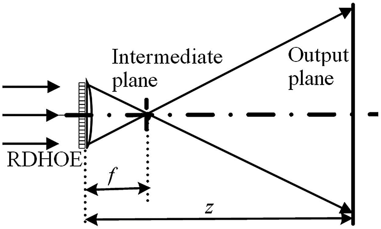
First, the RDHOE consisting of a DOE and a convex lens is used to generate a large diffraction pattern, and the incident beam is an ideal plane wave. The back focal plane of the concave lens is regarded as an intermediate plane, as shown in Fig. 1.
Figure 1.Scheme of the propagation from the RDHOE with a DOE and a convex lens to the output plane.
The complex amplitude distribution of the RDHOE (in one dimension for convenience) is , where is the focal length of the convex lens, is the complex amplitude distribution of the DOE, is the spherical phase factor introduced by the convex lens, and and is the incident wavelength. To accurately calculate the intensity distribution on the output plane, the calculation of the diffraction pattern on the output plane is divided into two steps.
The first step is to calculate the Fraunhofer diffraction from the RDHOE to the intermediate plane by[18]where represents Fourier transform and is the complex amplitude distribution on the intermediate plane. When the fast Fourier transform (FFT) is used here, the size of the diffraction pattern on the intermediate plane is determined by[19]where and are the sampling range and the sampling interval of the DOE, respectively. also denotes the size of the DOE. is the sampling interval on the intermediate plane and is the number of the sampling points.
The second step is to calculate the Fresnel diffraction varying from the intermediate plane to the determined output plane[18], where is the complex amplitude distribution on the output plane, and is the distance between the RDHOE and the output plane. The size of the diffraction pattern on the output plane is determined by[19]
From Eqs. (1) and (3), Equation (5) can be easily computed with an FFT.
The deduction of the backward propagation is similar. The phase distribution of the DOE can be optimized easily with the Gerchberg–Saxton algorithm[20]. The final expressions of , , and are where is the sampling interval on the output plane. When and are given, a large diffraction pattern can be obtained by decreasing as well as increasing , the smaller is, and the larger is.
When the RDHOE consisting of a DOE and a concave lens is used, the front focal plane of the concave lens is regarded as an intermediate plane, as shown in Fig. 2.; is the focal length of the concave lens.
Figure 2.Scheme of the propagation from the RDHOE with a DOE and a concave lens to the output plane.
The expression of the complex amplitude distribution on the output plane is the same with Eq. (5) since . The expression of , , and are
Figure 3 shows the relation between and by the developed algorithm with a convex and a concave lens when , and that by the traditional method when only a DOE is used (), respectively. The parameters are as follows: , , .
Figure 3.Relation between and by the developed algorithm with a convex and a concave lens and that by the traditional method when only a DOE is used.
Figure 3 indicates that large diffraction pattern can both be obtained by the developed algorithm with a convex lens and with a concave lens, and the magnification performance with a concave lens is better than that with a convex lens. There is an intersection point of line 2 and line 3. It is the distance where the sizes of the diffraction patterns by the developed algorithm with a convex lens and by the traditional method are the same. The distance is denoted by , which is determined by
Hence, it is only when is small enough to ensure that so that a large diffraction pattern may be obtained by the developed algorithm with a convex lens, and it is only when that a larger diffraction pattern can be obtained.
A 2D simulation and experiment are carried out here. The experimental setup is shown in Fig. 4. The combination of an SLM and a lens is used to simulate the RDHOE, for convenience. A Holoeye PLUTO reflective phase-only SLM is employed here, , , , and . Since the SLM is reflective, a system consisting of and is employed here, and the focal lengths of and are the same to ensure that the complex amplitude distribution on the back focal plane of is the same as that on the SLM. A lens is put on the back focal plane of . Then, the RDHOE with a DOE and a lens can be simulated.
The performance of the RDHOE consisting of a DOE and a convex lens is investigated first in the simulation and experiment. Under this circumstance, is a convex lens. The desired diffraction pattern on the output plane is shown in Fig. 5(a). The required size of the diffraction patterns is when is 800 mm, and the external diameter of the ring is 124 mm. According to Eq. (7), . The simulation and experimental results are shown in Figs. 5(b), 5(c), and 5(d), respectively. The experimental result shows that the external diameter of the ring is about 124 mm, which is consistent with the simulation result.
Figure 5.Simulation and experimental results of a convex lens: (a) the desired diffraction pattern, (b) phase distribution of the DOE, (c) simulation result, and (d) experimental result.
As a comparison, the simulation and experimental results with the traditional method () when only a DOE is used is shown in Fig. 6. The experimental setup is similar to Fig. 4 but without the use of . The largest diffraction pattern size is only 63.3 mm when is 800 mm in the simulation. Here, the external diameter of the ring is 60.4 mm. The experimental result shows that the external diameter of the ring is about 60 mm, which is consistent with the simulation result. Furthermore, the zero-order background noise, the bright rectangular in Fig. 6(c), introduced by the pixelated structure of the phase-only SLM is obvious in Fig. 6, and the zero-order background noise of the larger diffraction pattern obtained by the proposed method is weakened obviously because the zero-order background noise is focused on the focal plane of the lens and then spreads out rapidly with the increase of the diffraction distance. As is well known, the zero-order background noise of the DOE for beam shaping is very sensitive to the fabrication error and the incident wavefront distortion. With the RDHOEs, the tolerance of the DOE to fabrication error and incident wavefront distortion will be increased.
Figure 6.Simulation and experimental results of the traditional method: (a) phase distribution of the DOE, (b) simulation, and (c) experimental.
The experimental setup is similar to Fig. 4 when the performance of the RDHOE with a DOE and a concave lens is investigated. The only difference is that is replaced by a concave lens. According to Eq. (8), the desired size of the diffraction pattern is when , , and the external diameter of the ring is 132 mm, as shown in Fig. 7(a). The simulation and experimental results are shown in Figs. 7(b), 7(c), and 7(d), respectively. The experimental result shows that the external diameter of the ring is about 132 mm, which is consistent with the simulation result.
Figure 7.Simulation and experimental results of a concave lens: (a) the desired diffraction pattern, (b) phase distribution of the DOE, (c) simulation, and (d) experimental.
In conclusion, RDHOEs with a DOE and a lens are used to realize beam shaping with a large diffraction pattern of any form. As the component of the RDHOEs, the lens can not only be concave but also convex, and the algorithm is developed for the design of these two types of the RDHOEs. The use of the convex and concave lens provides alternative choices for the design of the RDHOEs to generate a large diffraction pattern of any form. In addition, with the proposed method, the unit size of the DOE can be increased and the high requirement of the fabrication of the DOE can be loosen.
Weidong Qu, Huarong Gu, Qiaofeng Tan. Design of refractive/diffractive hybrid optical elements for beam shaping with large diffraction pattern[J]. Chinese Optics Letters, 2016, 14(3): 031404