Abstract
In order to improve the precision of the laser–radio-frequency (RF) synchronization system from sub-picosecond to femtosecond (fs), a synchronization system between a picosecond laser and a 1.3 GHz RF generator has been developed based on a fiber-loop optical-microwave phase detector (FLOM-PD). Synchronization with fs-level (3.8 fs) rms jitter, integrated from 10 Hz to 1 MHz, is achieved for the first time, to the best of our knowledge, in this kind of configuration. This system will be used for the superconducting RF accelerator at Peking University.High-precision laser radio frequency (RF)/microwave synchronization has become one of the key techniques in the accelerator field, especially for the fourth-generation light sources and ultrafast pump–probe experiments, such as free electron lasers (FELs) and ultrafast electron diffraction (UED)[1–4]. For these facilities/experiments, high-quality electron bunches with low emittance, low energy spread, and short bunch length are required. The electron bunches are generated from a photocathode with a photoelectric effect, followed by electron bunch shaping, manipulation, and acceleration with RF accelerators. To produce high-quality electron bunches in acceleration[5] and to achieve femtosecond (fs)-level temporal resolutions in pump–probe experiments[6], fs-level synchronization should be achieved between photocathode driven lasers and accelerator RF signals.
Through more than a half century’s development, laser–RF synchronization systems based on an electronic phase detector have been achieved with typical residual timing jitter of , integrated from 10 Hz to 100 kHz, between the laser and RF signal[7]. It cannot meet the demands of accelerators nowadays. To solve the problem, a variety of laser–RF synchronization systems based on optical phase detectors have been developed with fs-level residual timing instabilities, which can be characterized by jitter and drift[8–15]. Most of these demonstrations were based on low-noise mode-locked Er-fiber lasers[8–13,15]. Mode-locked solid-state lasers (Nd:YAG[16], Yb:YAG[17], Nd:YVO4[18], Nd:YLF[19,20], and Ti:sapphire[21]), however, are widely used in small-to-middle-scale accelerators. Therefore, high-precision synchronization of the RF signal to the mode-locked solid-state laser is highly desirable. In early 2017, 10-fs-level synchronization was achieved between a fs Ti:sapphire laser and an RF signal[14]. However, fs-level synchronization between a picosecond laser and RF signal, which is very important for a superconducting RF accelerator, has not yet been reported. In this Letter, we design a modular phase-locked loop (PLL) based on the fiber-loop optical-microwave phase detector (FLOM-PD) to synchronize a picosecond laser to a 1.3 GHz RF signal. The out-of-loop phase noise is () at 10 Hz (1 MHz) offset frequency and the integrated rms timing jitter is 3.8 fs (10 Hz–1 MHz), which is limited by the AM-to-PM noise in the PLL bandwidth and the shot noise above the PLL bandwidth.
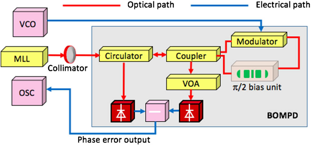
For high-precision synchronization between the RF and mode-locked picosecond laser, we develop two identical FLOM-PDs to detect and compensate for the phase error. Figure 1 shows a schematic of the FLOM-PD, which is based on a fiber Sagnac loop. All fibers used herein are polarization-maintaining single-mode fiber (PM-SMF) in order to improve the signal-to-noise ratio (SNR) of the FLOM-PD. As illustrated in the figure, an optical pulse train (in red) with a repetition rate of is coupled into fibers and propagates through a circulator. The pulse train is then split into two equal-power subpulses via a 50/50 coupler and interferes upon arrival back at the coupler. The intensities of the two outputs from the Sagnac loop are given by , and , where is the Sagnac-loop input optical power, and is the phase difference between counter-propagating pulses in the loop. An RF signal (in blue) with the frequency , which is sixteen times , copropagates with the clockwise optical pulse train. It results in either a retard or an advance in a traveling-wave phase modulator due to the electro-optic (EO) effect. The phase error between the laser pulse train and RF signal is then encoded in the relative phase difference between the counter-propagating laser in the loop.
Sign up for Chinese Optics Letters TOC. Get the latest issue of Chinese Optics Letters delivered right to you!Sign up now

Figure 1.Sketch of FLOM-PD. (MLL, mode-locked laser; OSC, oscilloscope; LPF, low-pass filter; VOA, variable optical attenuator; LNA, low noise amplifier; BOMPD, balanced optical-microwave phase detector).
In the FLOM-PD, a bias unit is employed to provide a phase shift of between the clockwise and counter-clockwise pulses to maximize its phase sensitivity. The output signal from the fiber Sagnac loop is detected by a balanced photodetector, which is used for precise optical-RF phase detection. The phase sensitivity of the FLOM-PD, proportional to the phase error between the optical pulses and the RF signal, can be expressed as , where is the transimpedance gain of the balanced photodetector, is the responsivity of the photodiodes, is the average optical power at either output port of the Sagnac loop, and is the modulation depth of the phase modulator.
To evaluate the residual phase noise and long-term timing drift of the laser–RF synchronization system, we set up an out-of-loop phase noise and timing drift measurement system together with a PLL. The experimental configuration is sketched in Fig. 2. As shown in the figure, two FLOM-PDs are used. One of them is combined with a loop filter and a proportional-integral controller (PIC) to form the PLL. Through the PLL, the 1.3 GHz RF signal from a voltage-controlled oscillator (VCO, E8663D, Agilent Technologies) is synchronized to the 81.25 MHz optical pulse trains from a commercial solid-state mode-locked laser (Time-Bandwidth GE-100-XHP). The other FLOM-PD is used for measurement. The output of this FLOM-PD is input into the signal spectrum analyzer (N9020, KEYSIGHT) and the data acquisition system to measure the residual phase noise and long-term timing drift, respectively.
Figure 2.Sketch of out-of-loop phase noise and timing drift measurement system. (SSA, signal spectrum analyzer; DAS, data acquisition system; LNA, low noise amplifier; PS, power splitter).
Figure 3 shows the single sideband (SSB) phase noise measurement results at 1.3 GHz carrier frequency and the corresponding integrated timing jitter, which represent the short-term instability of the synchronization system. The free-running absolute phase noise spectrum of the VCO was reproduced from the product manual[22]. The residual phase noise was measured by the in-loop and out-of-loop FLOM-PDs when the VCO was locked to the mode-locked laser. The measured out-of-loop phase noise is only higher than the in-loop phase noise. We attribute this to the different noise floor of the two FLOM-PDs that cannot be suppressed by the PLL loop. The out-of-loop integrated jitter from the 10 Hz to the 1 MHz loop bandwidth is about 3.8 fs rms. The noise floor is used to characterize the FLOM-PD’s limitations for phase detection, which is independent of the PLL’s limitations for the overall laser–RF synchronization.
Figure 3.(Color online) SSB phase noise (above) and integrated timing jitter (below).
Note that the out-of-loop phase noise is close to the noise floor of the FLOM-PD, which means the short-term jitter of the synchronization is dominated by the FLOM-PD’s noise performance in our experiments. Thus, it is important to analyze and improve the noise performance of the FLOM-PD. Figure 4 shows the noise source measurement/analysis results for the FLOM-PD. As shown in the figure, the noise floor of the FLOM-PD is almost 30 dB higher than the photodetector noise determined by the thermal noise. Therefore, the photodetector noise can be ignored. The FLOM-PD noise floor involves two dominant power-law noise processes: shot noise and AM-to-PM conversion noise. The shot noise, which is above PLL bandwidth (100 kHz) herein (see Fig. 4), can be suppressed by increasing the signal power. The AM-to-PM conversion noise is determined by the laser relative intensity noise (RIN) and the phase bias unit. In order to suppress the AM-to-PM conversion noise, a RIN controller[14] can be employed to improve the power stability of the laser. Replacing the free-space unit with fiber components can also be helpful, which contributes to improving the stability of the Sagnac loop[15].
Figure 4.(Color online) Analysis of FLOM-PD noise floor. The noise floor was measured with the RF phase modulation turned off. The photodetector noise (in gray) was obtained via direct measurement using a signal analyzer when the laser was off. The AM-to-PM conversion noise (in green) was calculated according to laser RIN[23]. The shot noise (red dashed line) and thermal noise (magenta dashed line) was calculated based on the experiment parameters.
Figure 5 shows the out-of-loop timing drift measurement results, which represent the long-term instability of the synchronization system. The measured rms timing drift is maintained at 126 fs (1 mrad at 1.3 GHz) within 5 h, which is equivalent to that achieved by electronics phase detectors most recently[7]. The drift is mainly caused by temperature drift and optical asymmetry in the phase bias unit. When the phase bias unit was removed, the measured timing drift was reduced to rms, close to the drift floor of the balanced photodetector.
Figure 5.Long-term timing drift measurements.
In conclusion, we synchronize a 1.3 GHz RF generator to a commercial picosecond laser with fs-level (3.8 fs) rms jitter, integrated from 10 Hz to 1 MHz, for the first time, to the best of our knowledge, by employing an FLOM-PD. The measured out-of-loop long-term timing drift is 126 fs rms within 5 h due to the temperature drift and optical asymmetry in the phase bias unit. In the near future, we will integrate the phase bias unit into a fiber component. With this improvement, we can expect a timing drift of several fs. This synchronization system can now fulfill the requirements of the operation of the superconducting RF accelerator at Peking University. Further improvement of the synchronization will promote the accelerator performance greatly for applications such as FELs, UED, etc.
References
[1] I. Grguraš, A. R. Maier, C. Behrens, T. Mazza, T. J. Kelly, P. Radcliffe, S. Düsterer, A. K. Kazansky, N. M. Kabachnik, Th. Tschentscher, J. T. Costello, M. Meyer, M. C. Hoffmann, H. Schlarb, A. L. Cavalieri. Nat. Photon., 6, 852(2012).
[2] E. Allaria, R. Appio, L. Badano, W. A. Barletta, S. Bassanese, S. G. Biedron, A. Borga, E. Busetto, D. Castronovo, P. Cinquegrana, S. Cleva, D. Cocco, M. Cornacchia, P. Craievich, I. Cudin, G. D’Auria, M. Dal Forno, M. B. Danailov, R. De Monte, G. De Ninno, P. Delgiusto, A. Demidovich, S. Di Mitri, B. Diviacco, A. Fabris, R. Fabris, W. Fawley, M. Ferianis, E. Ferrari, S. Ferry, L. Froehlich, P. Furlan, G. Gaio, F. Gelmetti, L. Giannessi, M. Giannini, R. Gobessi, R. Ivanov, E. Karantzoulis, M. Lonza, A. Lutman, B. Mahieu, M. Milloch, S. V. Milton, M. Musardo, I. Nikolov, S. Noe, F. Parmigiani, G. Penco, M. Petronio, L. Pivetta, M. Predonzani, F. Rossi, L. Rumiz, A. Salom, C. Scafuri, C. Serpico, P. Sigalotti, S. Spampinati, C. Spezzani, M. Svandrlik, C. Svetina, S. Tazzari, M. Trovo, R. Umer, A. Vascotto, M. Veronese, R. Visintini, M. Zaccaria, D. Zangrando, M. Zangrando. Nat. Photon., 6, 699(2012).
[3] R. P. Chatelain, V. R. Morrison, C. Godbout, B. J. Siwick. Appl. Phys. Lett., 101, 081901(2012).
[4] M. Gao, Y. Jiang, G. H. Kassier, R. J. Dwayne Miller. Appl. Phys. Lett., 103, 033503(2013).
[5] H. Schlarb, V. Ayvazyan, F. Ludwig, D. Noelle, B. Schmidt, S. Simrock, A. Winter. Proceedings of the 27th International Free Electron Laser Conference(2005).
[6] G. J. H. Brussaard, A. Lassise, P. L. E. M. Pasmans, P. H. A. Mutsaers, M. J. van der Wiel, O. J. Luiten. Appl. Phys. Lett., 103, 141105(2013).
[7] Q. Du, Y. C. Du, L. X. Yan, W. H. Huang, J. M. Li, C. X. Tang. Nucl. Instrum. Methods A, 637, S137(2011).
[8] J. Kim, F. X. Kärtner, F. Ludwig. Opt. Lett., 31, 3659(2006).
[9] J. Kim, J. A. Cox, J. Chen, F. X. Kärtner. Nat. Photon., 2, 733(2008).
[10] J. Kim, F. X. Kärtner. Opt. Lett., 35, 2022(2010).
[11] K. Jung, J. Kim. Opt. Lett., 37, 2958(2012).
[12] M. Y. Peng, A. Kalaydzhyan, F. X. Kärtner. Opt. Express, 22, 27102(2014).
[13] M. Walbran, A. Gliserin, K. Jung, J. Kim, P. Baum. Phys. Rev. Appl., 4, 044013(2015).
[14] H. Yang, B. Han, J. Shin, D. Hou, H. Chung, I. H. Baek, Y. U. Jeong, J. Kim. Sci. Rep., 7, 39966(2017).
[15] M. Xin, K. Şafak, M. Y. Peng, A. Kalaydzhyan, W. T. Wang, O. D. Mücke, F. X. Kärtner. Light: Sci. Appl., 6, e16187(2017).
[16] V. L. Flanchec, J. P. Bleses, S. Striby, J. P. Laget. Appl. Opt., 36, 8541(1997).
[17] J. Lu, X. Zou, C. Li, W. Li, Z. Liu, Y. Liu, Y. Leng. Chin. Opt. Lett., 15, 041401(2017).
[18] X. Fu, J. Li, X. Liang. Chin. Opt. Lett., 11, 081401(2013).
[19] A. R. Fry, M. J. Fitch, A. C. Melissinos, N. P. Bigelow, B. D. Taylor, F. A. Nezrick. Proceedings of the Particle Accelerator Conference, 2867(1997).
[20] Z. W. Wang, S. L. Huang, L. Lin, G. Zhao, S. W. Quan, K. X. Liu, J. E. Chen. Chin. Phys. C, 40, 017004(2016).
[21] K. Gumerlock, J. Frisch, B. Hill, J. May, D. Nelson, S. Smith. Proceedings of the Free Electron Laser Conference, 917(2014).
[22] . Data sheet of Agilent E8663D PSG RF analog signal generator(2016).
[23] J. Taylor, S. Datta, A. Hati, C. Nelson, F. Quinlan, A. Joshi, S. Diddams. Photon. J., 3, 140(2011).