Yueyu Xiao, Jinkui Yan, Lei Peng, Mingjue Tang, "Circularly polarizing fibers with a triple-lobe stress region," Chin. Opt. Lett. 14, 110606 (2016)
Copy Citation Text
A fiber structure with a circularly polarizing property is proposed. The fiber consists of a round core and a triple-lobe stress region in the cladding, which is compatible with single-mode fibers, and it can be fabricated using conventional metal chemical vapor deposition processes. By coating a layer with a high-refractive index, the twist pitch required for resonant coupling is increased to hundreds of micrometers, and the mature pit-in-jacket drawing technique can be used. The polarization filtering properties of the fabricated circularly polarizing fibers are measured experimentally, showing high distinction ratios in a broad frequency region.
The state of polarization of the light propagating in optical fibers needs to be controlled or manipulated for many fiber-optical applications. Although linearly polarized light is widely applicable, interest in the transmission of a stable, circularly polarized light in fibers dates back to 1970s, with the development of fiber-optical current sensors[1–3]. Besides the mechanically twisting fibers using the elasto-optic effect[4], pure circular birefringence can be achieved by a permanent twist of off-axis core fibers[5] or azimuthally segmented central core fibers[6,7] with twist pitches of several millimeters.
By eliminating both polarization mode coupling and polarization mode dispersion, polarizing fibers are desirable for applications requiring strict polarization management[8,9]. Many different structures of linearly polarizing (LPZ) fibers have been developed[10–12]. In 2004, Kopp proposed and demonstrated a type of fiber grating with circularly polarizing (CPZ) property, called chiral fiber gratings[13]. The polarizing mechanism of chiral fiber gratings is different from that of LPZ fibers. With twist pitches less than hundreds of micrometers, co-handed circularly polarized light will suffer a loss at certain wavelengths due to resonant couplings, while cross-handed circularly polarized light will pass through[14].
There are two types of polarization-sensitive chiral fiber gratings. One is chiral long-period gratings (CLPGs), which have a twist pitch of the order of 100 μm. However, the single polarization bandwidths of CLPGs are too narrow for most applications. The other is chiral intermediate-period gratings (CIPGs), which have a pitch of the order of 10 μm. The single polarization bandwidths of CIPGs are very broad, whereas such a short twist pitch increases the difficulty of fabrications, and only the microforming technique can create them[15]. The short twist pitches also increase the insertion losses and impair the mechanical strengths of the fabricated devices.
Sign up for Chinese Optics Letters TOC. Get the latest issue of Chinese Optics Letters delivered right to you!Sign up now
We have proposed that by coating a jacket with a high refractive index, the twist pitch of a double-helix chiral fiber can be increased to hundreds of micrometers, and the pit-in-jacket drawing technique can also be used. Therefore, fibers with circularly polarizing properties can be fabricated to tens or hundreds of meters, and we call them circularly polarizing fibers[16]. However, the rectangular core of the double-helix chiral fiber needs to be customized, and a mode adapter is indispensable[17]. In this Letter, we propose a new fiber structure with a circularly polarizing property. It consists of a round core and a triple-lobe stress region in the cladding, which is compatible with single-mode fibers, and it can be fabricated using conventional metal chemical vapor deposition (MCVD) processes[18]. Meanwhile, by coating a jacket with a high refractive index, the twist pitch required for the resonant coupling to the cladding leaky modes is of the order of hundreds of micrometers, and the mature pit-in-jacket drawing technique can be used. The polarization filtering properties of the fabricated CPZ fibers are measured experimentally, showing high distinction ratios in a broad frequency region.
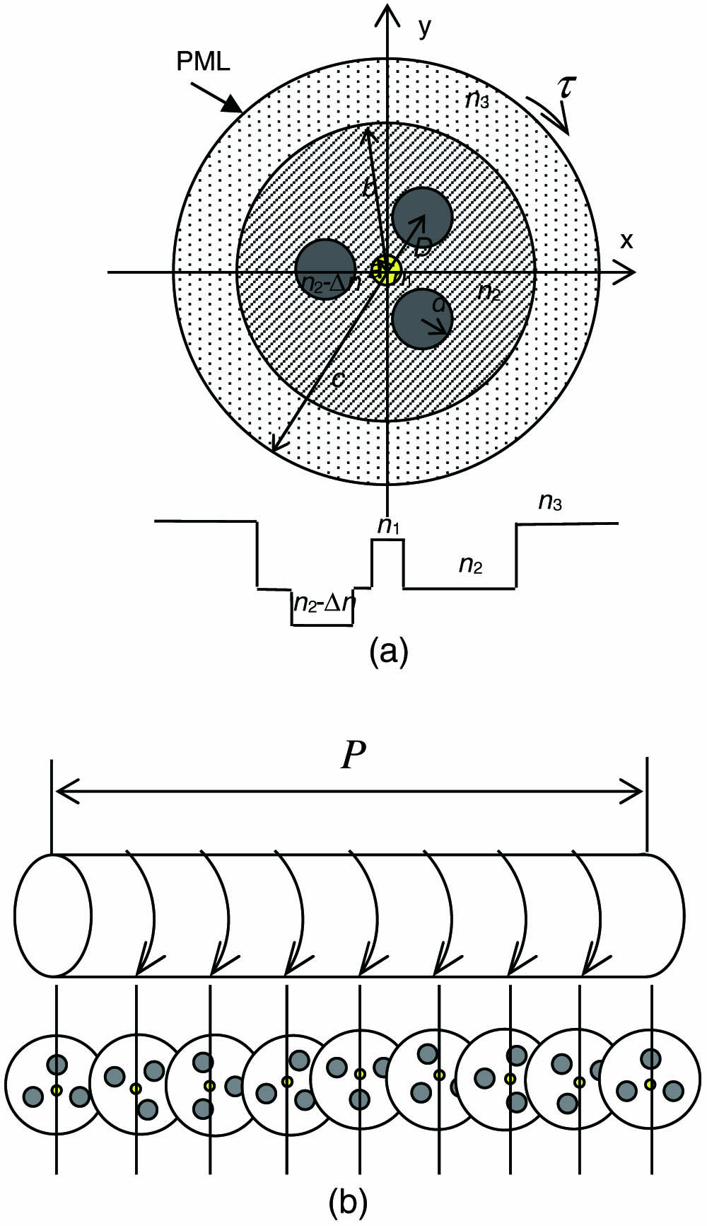
The cross section of the proposed CPZ fiber is shown in Fig. 1. It consists of a round core and an -lobe () stress region in the cladding, which can be fabricated using mature MCVD processes. The shape of the stress lobe is determined by the fabrication process. Since the stress rods are three-fold rotational symmetrically distributed, the intrinsic stress they produced is canceled out. Hence, the shape of the stress lobe makes no essential difference for the purpose of circular polarizing. We choose a circular shape for convenience in the analysis. The diameters of the core, the cladding, and the jacket are , , and , respectively. The diameter of the stress rod is . The distance between the center of the stress rod and the center of the fiber core is . The refractive indices of the core, the cladding, and the jacket are , , and , respectively. The stress lobe is boron-doped, with a refractive index difference with respect to the cladding. The CPZ fiber is fabricated by spinning the fiber preform while drawing. If the spinning speed of the preform is rpm and the speed of drawing is , the twist pitch is .
Figure 1.Schematic of the proposed fiber: (a) cross-sectional view and refractive index distribution and (b) side view.
When the refractive index of the jacket is higher than that of the cladding (), there are no discrete guiding modes in the cladding, only continuous radiation modes. No analytical solution of the coupled mode equation for the fiber grating can be obtained[19]. Koyamada gives an approximate solution only suitable for weak coupling[20]. Lu et al. proposed an approach to replace the open guide with a closed guide with a perfectly matched layer (PML), as shown in Fig. 1, which transforms the problem to the coupling between core modes and discrete leaky modes[21]. After adding a PML boundary, only the coupling of two synchronous modes is considered when the diameter of the cladding is μ: where and are the complex amplitudes of the core guiding mode and the cladding leaky mode, respectively. and are complex propagation constants, . The coefficients of the transversal coupling and longitudinal coupling are, respectively, where is the angular frequency of the light, is the distribution of the permittivity perturbation, and , , , and are the transversal and longitudinal fields of the core mode and the cladding mode, respectively. A spun fiber has periodicity not only along the direction of propagation but also on its cross-section. For the refractive index distribution of the fiber as shown in Fig. 1, the permittivity distribution with respect to the polar angle for a given polar radius is a constant when and and is a periodic function when :
When the fiber rotates around the core along the direction of propagation, we have , in which ± represents the right-hand and left-hand spiral structures of the fiber, and . Taking as the unperturbed waveguide, matching conditions for the left-hand spiral fiber are as follows: where and are the azimuthal periods of the cladding mode and the core mode, respectively. Generally speaking, the propagation constant of the core mode is larger than that of the cladding mode . The azimuthal matching condition is therefore for the first-order perturbation (). Only the left-hand fundamental core mode can couple to the right-hand cladding modes . That means in a frequency range where such coupling happens, the left-hand fundamental core mode is radiated, while the right-hand fundamental core is transmitted. The azimuthal matching condition is the mechanism of circular polarization selectivity.
If only the core mode is excited at the input end of the fiber [, ], the complex amplitudes of the left-hand core mode and the coupled cladding mode are where , , and . The transmittance of the left-hand core mode is
Similar to the long-period fiber grating, the transmission spectrum of the left-hand core mode is a series of loss peaks. The resonant wavelength is determined by
Transmittance of the core mode near the resonant wavelength is determined by parameters and . Increasing the coupling coefficient is an effective way to improve the polarization filtering properties of CPZ fibers. The distribution of the coupling coefficient as a function of distance and the radius of the stress rod are shown in Fig. 2. The fiber core radius is set to be μ, and the cladding and the jacket are , , and . The refractive index difference between the stress rod and the cladding is . The maximum value of is obtained when μ and μ, marked as point A in Fig. 2. In this case, the effective refractive indices of the left-hand core mode and the coupled cladding mode are and , respectively. The calculated pitch from Eq. (8) is μ, much greater than that of the CIPG. It is well known that the more quickly the refractive index changes along the fiber, the more loss is induced by the modal mismatch. Moreover, a small pitch means either a low drawing speed or a high spinning speed. Both slow drawing and fast spinning make the process control more difficult and increase fiber attenuation. The transmittance spectrum evolution along the fiber with the parameters of point A is shown in Fig. 3. It is observed that when the fiber is 1 m long, the transmittance of the left-hand core mode is less than for wavelengths between 1540 and 1560 nm.
Figure 2.Contour of coupling coefficient with respect to and .
The CPZ fiber proposed is drawn from a spinning perform using a modified pit-in-jacket technique. The preform was mounted in a chuck attached to a spinning motor, capable of rotating at 2000 rpm. The twist pitch is controlled by adjusting the linear drawing speed and drawing rate. The preform is prepared by conventional MCVD processes, similar to those of fabricating a bow-tie fiber. A CPZ fiber of tens of meters was fabricated, and Fig. 4 shows clearly the helical structure of the fabricated CPZ fiber, with the spun pitch of about 750 μm. The three stress rods rotate around the core.
The polarization properties of the fabricated CPZ fibers were measured with the Jones matrix method[22]. Figure 5 shows the experimental setup. A wavelength-tunable DFB laser was used as the source, covering a range of wavelengths from 1530 to 1560 nm. The output light was guided to the polarization controller by a converging lens and then guided into the tested CPZ fiber by another converging lens. The SOP of the output light from the CPZ fiber was measured with a polarimeter.
Figure 5.Experimental setup of the Jones matrix method.
It is well known that for an optical device with two orthogonal polarization eigenstates and , the output state of polarization can be written as where is the input state of polarization, is the propagation distance within the optical device, and represents the complex propagation constant of the th polarization eigenstate. Thereby, the Jones matrix of the optical device can be decomposed to where , and is a diagonal matrix:
If the two polarization eigenstates suffer different losses within the optical device, the extinction ratio of the two orthogonal polarized lights is determined by
When injecting three linearly polarized lights, whose polarization orientations are parallel to the -axis, perpendicular to the -axis, and with a 45° angle to the -axis, into a 1-m-long CPZ fiber, the output polarization ellipses are as shown in Fig. 6. The Jones matrix of the CPZ fiber () can be obtained. The two orthogonal polarization eigenstates of the CPZ fiber are illustrated in Fig. 7, with the ellipticities of 0.92 and 0.93. By adjusting the wavelength of the input light from 1530 to 1560 nm, we obtain the extinction ratios of the two circularly polarized lights, as shown in Fig. 8. The extinction ratios are all near 30 dB for the wavelengths used in the measurement, showing a broad-band circular polarization filtering property of the CPZ fiber.
Figure 6.Output polarization ellipses when three linearly polarized lights with different orientations are injected into the CPZ fiber.
We propose and demonstrate a new structure of the fiber that possesses the property of circular polarizing. It consists of a round core and a triple-lobe stress region in the cladding, which is compatible with single-mode fibers, and it can be fabricated using conventional MCVD processes. By coating it with a high refractive index jacket, the twist pitch is increased to hundreds of micrometers, and the mature pit-in-jacket technique can be used. The polarization filtering properties of the fabricated fiber are analyzed theoretically and measured experimentally, showing high distinction ratios in a broad frequency region.
References
[1] A. J. Rogers. Proceedings of the Institution of Electrical Engineers, 120, 261(1973).