H. Ahmad, I. S. Amiri, A. Z. Zulkifli, H. Hassan, R. Safaei, K. Thambiratnam. Stable dual-wavelength erbium-doped fiber laser using novel fabricated side-polished arc-shaped fiber with deposited ZnO nanoparticles[J]. Chinese Optics Letters, 2017, 15(1): 011403
Copy Citation Text
A dual-wavelength fiber laser operating at the 1550 nm region using a side-polished arc-shaped fiber with deposited ZnO nanoparticles is proposed and demonstrated. The arc-polished fiber is fabricated by using a simple but novel approach in which a silicon carbide paper polishes one side of a conventional single-mode fiber. An arc-polished fiber with a length of 2.25 mm and an insertion loss of 0.95 dB is obtained and deposited with ZnO nanoparticles by the drop-cast method. A stable dual-wavelength output is obtained at 1562.5 and 1563.4 nm at peak powers of and , respectively, as well as a signal-to-noise ratio of 28.4 dB and a channel spacing of 0.9 nm. Both lasing wavelengths also have narrow linewidths of between 0.045 and 0.049 nm and show little to no wavelength or power fluctuations over continued testing.
The exploitation of the evanescent field of signals traveling through an optical fiber provides a number of useful and interesting applications[1,2].
The design with the most potential is one in which the cladding layer is thin enough that the evanescent field can overcome it to interact with external elements. This fiber design is known as a D-shaped fiber[3], in which the cladding surrounding the fiber's core has a D-shaped geometric profile, with one side of the cladding being so thin that it allows the evanescent field to expand beyond the cladding, while still containing the rest of the signal in the core. Furthermore, the use of the D-shaped fiber makes this approach very cost effective and easy to deploy[4]. Removing a portion of the cladding from the fiber provides various additional advantages, including low mode-locking threshold and a high-power operation[5,6].
One of the possible applications of the D-shaped fiber is that it provides a platform in which various materials can be deposited, thus allowing for various optical phenomena as the evanescent field interacts with these materials. This includes the passive generation of pulses as well as non-linear optical phenomena such as Brillouin scattering[7–9]. Of specific interest would be the generation of multi-wavelength source. Multi-wavelength sources allow for all generated signals to share similar phase characteristics, which is crucial especially for characterization applications, and to have narrow linewidths and high powers[10–18]. Dual-wavelength sources in particular are especially useful for the generation of high bit rate soliton pulse trains[19,20], as well as producing optical pulses with high repetition rates[21].
Sign up for Chinese Optics Letters TOC. Get the latest issue of Chinese Optics Letters delivered right to you!Sign up now
Interestingly enough, there has been very little work done on the generation of a dual-wavelength output using D-shaped fibers. This is due to a number of limitations inherent to D-shaped fibers, including asymmetrical geometries that show a reasonable directional bend sensitivity[22]. Thus, a new approach that can overcome these limitations is necessary. In this manner, the addition of nanostructures onto the flat side of a side-polished D-shaped fiber provides a viable solution. Such approaches have already been successfully demonstrated, such as by Han[23], who showed the generation of a multi-wavelength output by the interaction of the evanescent field with carbon nanotubes deposited on a D-shaped fiber, while Lee et al.[24,25] demonstrated the use of graphene oxide deposited on the flat surface of a side-polished fiber to obtain stable -switched and mode-locked outputs.
This work is the first demonstration, to the best of our knowledge, of a very inexpensive method of polishing an arc-shaped fiber that has similar behavior to a D-shaped fiber. The self-fabricated arc-shaped fiber with deposited ZnO nanoparticles is demonstrated in a dual-wavelength fiber laser (DWFL) configuration. The setup utilizes a conventional erbium-doped fiber (EDF) as the gain medium, with the arc-polished fiber generating the desired dual-wavelength output through constructive multi-mode interference induced by the cavity loss of the arc-polished fiber. The proposed system is a compact and robust dual-wavelength source that is also highly cost effective.
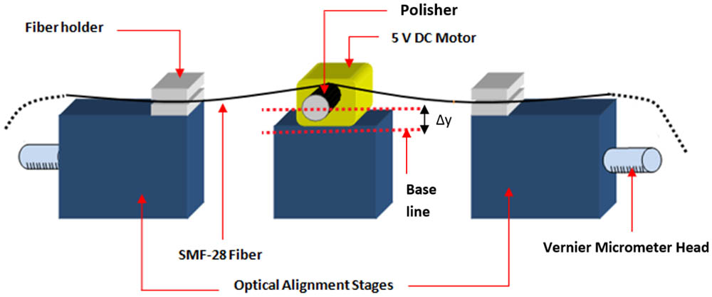
The setup of the arc-polisher assembly is shown in Figs. 1 and 2. The system consists of two optical alignment stages and the polisher stage, which holds the motorized polisher. The stages are two Newport M-562-D stages with Newport 561-FH fiber holders, which are used to secure the single-mode fiber (SMF-28) that will be polished. The polisher assembly consists of a Newport M-561D alignment stage with a standard 5.0 V direct current (DC) motor that is secured on top of the stage. The motor has a measured maximum speed of 6100 revolutions per minute (RPM) and a torque of and has a sheet of silicon carbide with a grain size of 1000 securely wrapped around the exposed shaft of the DC motor, which is about 0.9 cm in diameter and now acts as the polisher. The polishing assembly lies perfectly perpendicular to and exactly in between the other two stages.
Figure 1.Schematic of the arc-polisher assembly setup.
The height of the polisher can be raised in steps of 10 μm by rotating a Newport, SM-13 Vernier micrometer heads, and is initially kept lower than the fiber holders. To fabricate the polished fiber, the SMF-28 is prepared by first “stripping” away the polymer layer of the fiber along a selected portion of the fiber, leaving only the cladding and the core. The SMF-28 is then secured in place on the two stages, with the “stripped” portion of the fiber above the polisher. The polisher height is adjusted in such a manner that the polisher can come into contact with and bend the SMF-28 fiber. The amount of bending done to the fiber is governed by the height from the center of the polisher with respect to the baseline, which is denoted as , as shown in the schematic. Hence, the baseline is defined as an offset center of the polisher height when the fiber is perfectly straight and touches the polisher. In this case, is adjusted to a value of 1000 μm. The polisher is rotated at about 4500 RPM at a drive voltage of 3.6 V to polish the fiber.
Figure 2 shows the actual assembly, with the SMF-28 fiber in place for polishing.
During the polishing process, it is difficult to physically observe the SMF-28. As such, a different mechanism needed to be developed to monitor the fiber during the polishing process. A red laser light at a power of 10 mW is launched into one end of the fiber during the polishing process. Once a red light is observed to be leaking out at the fiber-polished site, the polishing process is discontinued. The whole process takes about 15 min to accomplish, and an insertion loss of 0.95 dB is obtained. Figure 3 shows the SMF-28 before and after the polishing process.
Figure 3.Microscope images of (a) the unpolished SMF-28 fiber and (b) the arc-polished fiber.
Using this method, a 2.25 mm length of polished fiber is acquired. In order to avoid inducing the losses that can arise if there is a direct interaction between the evanescent field of the guided mode and the imperfect fiber surface, the cladding between the off-centered core and the air should have a thickness greater than a few micrometers[26].
Figure 4 shows the interaction between the cylindrical polishing shaft and the SMF-28 fiber being polished.
Figure 4.(a) Optical fiber schematic, where is the core radius, is the cladding diameter, is the penetration depth, and is the cylindrical polisher’s radius. (b) Ray tracing of the side-polished fiber. is the effective mode radius.
With this approach, the propagating modes can be transformed into radiation modes linked to the cutoff penetration depth (), in which the cylindrical penetration depth exceeds certain critical values. A meridional angle of incidence and an effective mode radius correspond to each mode of the radial order and the azimuthal order [27,28], where the propagation constant is defined by for the lm mode, the enlargement caused by the Goos–Hanchen shift is defined as , and is the wave number. Assuming that , the TE and TM modes have the same enlargement, which can be calculated from following equation[29], Thus, if, the silicon carbide paper comes into contact with the SMF-28 at , then the reflection’s angle becomes , where is the angle between the tangential plane to the silicon carbide paper surface and the -axis. It will then impinge on the diametrically opposite interface with an angle of incidence in relation to the normal to the interface. Therefore, by changing the surface thickness, the angle of incidence will move toward the critical angle. The cutoff angle can be calculated by where is the total internal reflection. The cutoff penetration depth () therefore can be calculated as The ZnO nanoparticles solution that was to be deposited onto the polished fiber was provided commercially. The solution was drop-casted onto the arc-polished fiber and left to dry for 1 h before use. Measurements of the insertion loss and polarization-dependent loss of the polished fiber with the ZnO deposited nanoparticles give values of 1.04 and 0.063 dB, respectively.
The setup of the proposed DWFL is illustrated in Fig. 5. The system consists of a 3 m long M12 Metrogain EDF from Fibercore. The EDF has an absorption coefficient of 11.3 dB/m at a wavelength of 979 nm, along with a mode field diameter of 6.6 μm and a numerical aperture (NA) of 0.21. The EDF is backward-pumped by a 1480 nm Fitel FOL140ZPLE-417 laser diode (LD) through the 1480 nm port of a 1480/1550 nm wavelength-division multiplexer (WDM). The EDF is connected to the common port of the WDM and again to another similar WDM at its other end. The second WDM serves to remove any excess pump power from the laser cavity to optimize the performance of the system. As the EDF is pumped by the LD, it generates an amplified spontaneous emission (ASE) spectrum, which now travels back towards the first WDM and is then directed through the 1550 nm port, where it now encounters the polished fiber deposited with the ZnO nanoparticles. An enhanced wavelength-dependant loss filter assisted by ZnO on the side-polished fiber results in a stable dual-wavelength output being formed. The generated dual-wavelength output now travels along the cavity, where it encounters an 80:20 tap coupler, which extracts 20% of the signal for analysis. The remaining 80% continues to travel along the cavity, passing through an optical isolator to ensure unidirectional travel before finally completing the cavity through the 1550 nm port of the second WDM.
Figure 5.Experimental setup for the dual-wavelength generation.
The signal extracted from the cavity through the 20% port of the 80:20 coupler is now divided into two equal portions using a 50:50 coupler. This is done to attenuate the optical power of the DWFL output by 50%, thereby allowing it to be safely measured by an Anritsu MS9740A optical spectrum analyzer (OSA).
Figure 6 shows the unstable multi-wavelength laser spectra measured at a resolution of 0.05 nm and a span of 10.0 nm without the ZnO layer deposited on the arc-shaped side-polished fiber at time intervals of 2 min. The spectra were obtained at an LD power of 10.3 mW. It can be observed that the lasing wavelengths often shift due to the mode-competition effect, together with the weak wavelength-dependent loss filter of the fabricated side-polished fiber. A comb-like pattern is also observed in the spectra due to the multi-mode interference effect.
Figure 6.Unstable multi-wavelength fiber laser spectra obtained without the presence of the ZnO layer on the side-polished fiber at 2-min intervals.
The ASE transmission spectra of the side-polished fiber with and without the ZnO layer deposited onto the polished site are shown in Fig. 7. For both spectra, the launch power is about −7.5 dBm, and both measurements are taken using the same OSA settings. A drop in power is observed when the ZnO layer is deposited onto the arc-shaped side-polished fiber.
Figure 7.ASE transmission spectra of the arc-shaped side-polished fiber with and without the ZnO layer.
Figure 8 shows a stable DWFL spectrum with ZnO deposited on the side-polished fiber at a pump power of 10.3 mW at the same measurement setting. From Fig. 8, it can be seen that two wavelengths oscillate in the cavity at wavelengths of 1562.5 and 1563.4 nm, with corresponding peak powers of and , respectively. The spacing between the two oscillating wavelengths are approximately 0.9 nm, and the peaks have an average signal-to-noise ratio (SNR) of 28.4 dB. Both wavelengths have narrow 3 dB linewidths, with the shorter lasing wavelength having a linewidth of 0.049 nm, and the longer wavelength having a 3 dB linewidth of 0.045 nm.
The stability of the dual-wavelength lasing output from the DWFL is given in Figs. 9–11. Figure 9 shows the time spectrum of the dual-wavelength output taken at intervals of 2 min over a total duration of 12 min. The corresponding laser peak powers and wavelengths over the same period of time and taken at the same time intervals are plotted in Figs. 10 and 11. It can be seen that overall, the output of the DWFL is highly stable, with almost no change in the shape or peak values of the spectrum. This indicates there is no fluctuation in the power or wavelength of the laser output, nor are there any indications of sudden spikes in power. This is further validated by Figs. 10 and 11, which clearly indicate that the wavelength and power of the output signals do not change significantly. The wavelength has a calculated maximum standard deviation of approximately , while the highest peak power difference is approximately 1.03 dB.
The proposed laser would have significant real-world applications, particularly for applications that require narrowly spaced wavelengths, such as sensor and reference signals sources[30,31] or multi-wavelength sources[32], and also in the generation of new laser sources that exploit various non-linear optical phenomena, such as four-wave mixing[33]. The arc-polished fiber also provides a new platform on which various materials, such as ZnO nanoparticles, can be deposited, allowing for the exploration of new applications, such as the generation of passively pulsed outputs or even the exploitation of various non-linear phenomenon such as Brillouin scattering. Thus, the proposed DWFL will provide a compact and cost-effective platform for a variety of new applications.
The ZnO layer used here is very thin, thus preventing it from acting as a saturable absorber. Thus, the ZnO nanoparticles serve only to stabilize the output of the DWFL as compared to other works, in which the ZnO nanoparticle layer is thicker and thus acts as a saturable absorber[34].
In conclusion, a DWFL utilizing an arc-polished fiber with deposited ZnO nanoparticles and a conventional EDF is proposed and demonstrated. The arc-polished fiber is fabricated in-house using a custom-built polisher and deposited with ZnO nanoparticles using the drop-cast method. The 2.25 mm long arc-polished fiber is then incorporated into the laser with a 3 m long EDF pumped by a 1480 nm LD to generate a stable dual-wavelength output with lasing wavelengths at 1562.5 and 1563.4 nm, with narrow linewidths of 0.045 and 0.049 nm. The lasing wavelengths have powers ranging between and , with a signal-to-noise ratio of 28.4 dB, and show little to no fluctuation in power or wavelength during continued testing of the output pulses. The proposed system would have significant applications in a variety of sensor tasks, especially those that require the use of reference signals in a compact and cost-effective platform.
References
[1] Z. Cai, T. Guo, F. Liu, B.-O. Guan, G.-D. Peng, J. Albert. Proc. SPIE, 9634, 96344I(2015).
[2] Y. Zhang, J. Fan, J.-Q. Liang, J. Ma, G. Chen, S. Jia, F. Nori. Sci. Rep., 5, 11510(2015).
[3] J. Zapata, D. Steinberg, L. Saito, R. de Oliveira, A. Cárdenas, E. T. de Souza. Sci. Rep., 6, 20644(2016).
[4] Z. Cai, L. Fu, B.-O. Guan, G.-D. Peng, J. Albert. Asia Communications and Photonics Conference, AM1I. 6(2015).
H. Ahmad, I. S. Amiri, A. Z. Zulkifli, H. Hassan, R. Safaei, K. Thambiratnam. Stable dual-wavelength erbium-doped fiber laser using novel fabricated side-polished arc-shaped fiber with deposited ZnO nanoparticles[J]. Chinese Optics Letters, 2017, 15(1): 011403