Abstract
A multi-wavelength sampled Bragg grating (SBG) quantum cascade laser array operating between 7.32 and 7.85 μm is reported. The sampling grating structure, which can be analyzed as a conventional grating multiplied by a sampling function, is fabricated by holographic exposure combined with optical photolithography. The sampling grating period was varied from 8 to 32 μm, and different sampling order (st, nd, and rd order) modes were achieved. We propose that higher-order modes with optimized duty cycles can be used to take full advantage of the gain curve and improve the wavelength coverage of the SBG array, which will be beneficial to many applications.1. INTRODUCTION
In recent years, quantum cascade lasers (QCLs) as mid-infrared optical sources have attracted much attention for applications including gas sensing, industrial process monitoring, spectroscopy, and free space communication [1–3]. Widely tunable single-mode QCLs with high power and side mode suppression ratio (SMSR) are highly desired for many applications. Single distributed feedback (DFB) QCL has a very limited tuning range (less than ), which limits its usefulness for broadband spectroscopy. There are mainly three types of widely tunable QCLs being developed, that is, external cavity (EC) QCLs [4], an array of DFB-QCLs [5,6], and dual section sampled grating/slot waveguide QCLs [7–9]. Among them, EC-QCLs are widely used as reliable broadly tunable equipment. However, they are usually bulky and require high-precision optical alignments. The DFB-QCL array has achieved an impressive tunability over , but this array needs electron beam lithography to create different grating periods in the same chip, which is expensive and time-consuming. As for dual section sampled grating QCLs [7,8], the Vernier-like tuning mechanism leads to a limited tuning range and usually produces the edge mode due to the supermode selection.
The sampled Bragg grating (SBG) is an effective way to achieve wavelength tuning by changing the sampling periods, which has been demonstrated in Refs. [10,11]. The sampled grating can be analyzed as a conventional grating multiplied by a sampling function. By altering the sampling periods in one chip, multi-wavelength QCL arrays can be achieved. To stabilize the lasing wavelength, equivalent phase shift (EPS) of quarter-wave () [12,13] and antireflection (AR) coating can be applied to enhance the side-mode-suppression ratio and prevent mode hopping. To improve the heat dissipation, epi-side-down bonding on patterned submount has also been utilized [14].
In this paper, we designed and fabricated an array of 18 buried SBG-QCLs on a single chip. The sampling grating period was varied from 8 to 32 μm, and different sampling order (st, nd, and rd order) modes were achieved. Single-mode emission at different wavelengths (from 7.317 to 7.851 μm) with an SMSR about 20 dB was obtained in pulsed mode at room temperature. The emitting wavelength covered a total spectral range of 534 nm (), and the peak output power varied between 94 and 176 mW. We propose that higher-order modes with optimized duty cycles can be used to take full advantage of the gain curve and improve the wavelength coverage of the SBG array, which will be beneficial to many applications.
Sign up for Photonics Research TOC. Get the latest issue of Photonics Research delivered right to you!Sign up now
2. DEVICE DESIGN AND FABRICATION
The basic principle of SBG is that the sampling grating introduces an additional periodicity, which results in a comb of evenly spaced reflectivity peaks centered at the wavenumber determined by the period of the base grating. The equation can be expressed as [15] where is the Bragg wavelength of the base grating, , are the wavelengths of the st and nd order modes, is the effective refractive index of the waveguide, and and represent the periods of base grating and sampling grating, respectively. Thus, is inversely proportional to . Normally we set the st order wavelength around the peak of the gain curve, while the Bragg wavelength was set at the edge. However, in order to make full use of the gain curve, has to be small, which makes the fabrication more complex. If we optimize , making the nd or rd order modes at the center of the gain curve, the base and st order modes will be suppressed due to the lack of adequate gain. Figure 1 shows the electroluminescence (EL) spectrum (lower curve) of the fabricated wafer, measured at room temperature with a pulse width of 1 μs and repetition frequency of 10 kHz. The peak of the gain curve is about 7.57 μm with a full width at half-maximum (FWHM) of about 600 nm. The calculated of the epitaxial structure is about 3.18. The period of the base grating and the Bragg wavelength were set to be 1.38 μm and 8.8 μm, respectively. The period of the sampling grating was varied from 8 to 32 μm. The upper curve shown in Fig. 1 is the transmission spectrum based on transfer matrix simulation with the sampled grating period of 20.7 μm, which is an integer multiple of the base grating period. For ensuring stable single-mode emission, similar to Ref. [13], we employed an EPS of quarter-wave (), which makes the emission from the defect mode.
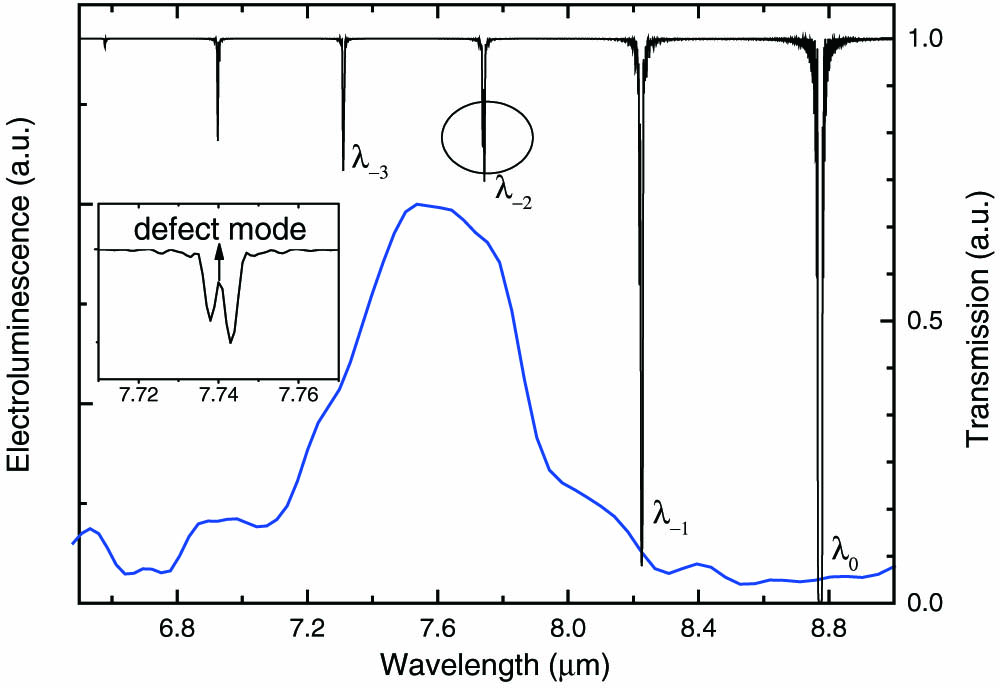
Figure 1.EL spectrum and the calculated transmission spectrum. The inset displays the enlarged nd order mode in the transmission spectrum. The defect mode introduced by EPS can ensure stable single-mode emission.
The QCL core structure was grown on an -InP substrate by solid-source molecular beam epitaxy (MBE), and the InP layers were grown by metal-organic chemical vapor deposition (MOCVD). The epitaxial layer sequence, starting from the -doped InP substrate, was as follows: 4 μm doped bottom InP cladding layer (Si, ), 0.3 μm doped layer (Si, ), QCL active core, 0.3 μm upper layer, 3 μm low doped upper InP waveguide (Si, ), 0.2 μm gradually doped InP layer (Si, from to ), and 0.6 μm highly doped InP contact layer (Si, ). The QCL active core is based on the bound to continuum design and comprises 50 periods with and as the quantum wells and barriers, respectively. The layer sequence in one period (in angstroms) from the injection barrier, 40/17/9/50.6/9/47/10/39/18/32/17/28/19/27/28/26, where the bold represents barriers and the underlined are layers with Si doped to . The base Bragg grating was defined on the upper InGaAs confining layer using holographic lithography and transferred by wet chemical etching to the depth of 200 nm. The sampling grating with EPS was formed by conventional optical photolithography. After the re-growth of the InP layer, optical photolithography and nonselective wet chemical etching were used to form the SBG array, which has 18 channels separated by 90 μm. The mean core width of each ridge is about 12 μm. A 450-nm-thick layer was deposited for insulation around the ridges. An electrical injection window with 6 μm width was opened on the ridges, and the top Ti/Au electrical contact was deposited by electron beam evaporation. An additional 5-μm-thick gold layer was subsequently electroplated to further improve heat dissipation. Then 50-μm-wide electrical isolation trenches between the adjacent sampling ridges were defined by wet etching the Au/Ti layer. After thinning down the substrate to about 120 μm, Ge/Au/Ni/Au was deposited as the substrate contact layer. The processed wafer was cleaved to a 3-mm-long laser arrays. High-reflectivity (HR) coating consisting of (200/10/100/10/120 nm) and AR coating of (650/78 nm) were also evaporated at the rear facet and the front facet, respectively. The AR coating is used to improve the single-mode selection. At a wavelength of 7.6 μm, the refractive indices of and Ge are 1.382 and 4.006, respectively. The deposited (650/78 nm) AR coating has a nominal reflectivity below . The patterned AlN submount was fabricated to realize epitaxial down bonding [14]. Figure 2(a) shows the microscope image of the SBG-QCL array, which was epi-side-down bonded on the patterned AlN submount. Figure 2(b) shows the magnified view of the front facet of the laser array. The distance between the adjacent laser ridges is 90 μm. Figure 2(c) shows the scanning electron microscope (SEM) image of the sampled grating.

Figure 2.(a) Optical microscope image of SBG-QCL array bonded on patterned AlN submount; (b) magnified view of the front facet of the array; (c) SEM image of the sampled grating.
3. DEVICE CHARACTERIZATION AND DISCUSSION
The SBG-QCL array was wire bonded and mounted on a holder containing a thermistor combined with a thermoelectric cooler (TEC) to monitor and regulate the temperature, respectively. The emitted optical power and spectra from the AR-coated side of the array were measured with a calibrated thermopile detector placed directly in front of the laser facet and a Fourier transform infrared (FTIR) spectrometer, respectively. All measurements were taken under pulsed operation at a duty cycle of 1% with 1 μs pulses at room temperature. As shown in Fig. 3, the array with 18 lasers covers a wide spectral range of 534 nm varying from 7.317 μm () to 7.851 μm (). Single-mode operation with an SMSR about 20 dB was obtained for all measured spectra. Among the array, lasers #1–10, #11–14, and #15–18 were emitting from the first-order, second-order, and the third-order modes, respectively. It is noted that mode hop occurred for the #12 laser, which will be discussed later.
Figure 3.Measured spectra of the 18 SBG-QCLs from an array with different sampling periods ranging from 8 to 32 μm (from bottom to top).
As an example, Fig. 4(a) shows the temperature-dependent spectra of laser #6 in the array under pulsed operation with a 1% duty cycle. The heat sink temperatures were varied from 20°C to 55°C with the increment of 5°C. The center wavelengths changed from at 20°C to at 55°C, with the tuning coefficient of , as illustrated in the inset of Fig. 4(a). Single-mode operation was maintained at all measured temperatures with an SMSR about 23 dB. Figure 4(b) shows the power-current-voltage (P-I-V) measurement for laser #6 at 20°C. Peak power about 150 mW was obtained. The slope efficiency was around 280 mW/A. The sampling periods, lasing wavelengths, and peak output powers of all 18 lasers in the array were summarized in Table 1. The output powers varied between 94 and 180 mW.
Figure 4.(a) Measured spectra of laser #6 in the array at different heat sink temperatures from 20°C to 55°C. The inset shows the tuning of the peak wavenumber with temperature. (b) The P-I-V characteristics of laser #6 in the array.
| Laser | Sampling Period Z (μm) | Wavelength λ (μm) | Power (mW) | Laser | Sampling Period Z (μm) | Wavelength λ (μm) | Power (mW) |
| 1 | 8 | 7.454 | 154 | 10 | 12.5 | 7.852 | 152 |
| 2 | 8.5 | 7.521 | 180 | 11 | 14.5 | 7.358 | 152 |
| 3 | 9 | 7.579 | 108 | 12 | 16 | 7.448 | 146 |
| 4 | 9.5 | 7.628 | 172 | 13 | 17 | 7.527 | 115 |
| 5 | 10 | 7.672 | 151 | 14 | 19 | 7.590 | 94 |
| 6 | 10.5 | 7.710 | 150 | 15 | 21 | 7.316 | 140 |
| 7 | 11 | 7.752 | 155 | 16 | 24 | 7.464 | 122 |
| 8 | 11.5 | 7.786 | 140 | 17 | 28 | 7.615 | 176 |
| 9 | 12 | 7.846 | 158 | 18 | 32 | 7.737 | 164 |
Table 1. Detailed Values of the Sampling Period, Emitting Wavelength, and Output Power for All 18 Lasers
The normal sampled grating transmission spectrum did not consider the situation when the sampling period is not an integer multiple of the base grating period . As shown in the inset of Fig. 5, A is the region with base grating in one sampling period, and B is the region without grating. We can see that the translational symmetry of A breaks down at the edge. This will produce an extra phase shift between the adjacent sampling periods and break the periodicity of the ideal sampling periods. By refining the meshing of the model of the transfer matrix method (TMM), we calculated the effect of the phase shift in the transmission spectrum. Figure 5 shows the transmission spectrum with a sampling period of 19 μm, and the Bragg period was maintained at 1.38 μm. Compared to Fig. 1, we can see that the extra phase shift contributes to additional transmission modes, which correspond to the extra Fourier components of the effective refractive index profile, other than the normal sampling order. This may influence the stability of the emission mode, as mode hopping has been observed for the #12 laser.
Figure 5.Calculated transmission spectrum with a sampling period of 19 μm and base grating period of 1.38 μm. The inset illustrates the breakdown of the translational symmetry.
We also calculated the coupling coefficient of sampled grating DFB-QCL. According to the coupled-mode theory of DFB lasers, the coupling coefficient can be approximately written as where represents the modulation of the absorption coefficient, and is the amplitude of the periodic modulation of the real part of the effective refractive index. It is usually considered that the sampled grating coupling coefficient is simply given by the product of the coupling coefficient of the uniform grating times of the duty cycle of the superstructure [16,17]. However, it is only applicable for the zero-order mode and not suitable for the first-, second-, and third-order modes. For a finite cavity length, the refractive index can be Fourier expanded as Here is the index modulation at a particular wavelength . We calculated of the zero-, first-, second-, and third-order modes as a function of duty cycle at a fixed cavity length of 3 mm and sampling period of 20 μm. The results were shown in Fig. 6. For the zero-order mode, is linear to the duty cycle, which means the greater the duty cycle, the stronger the refractive index coupling. For the first-order mode, the maximum coupling is at the duty cycle near 0.5. The curve of versus duty cycle is significant for designing the duty cycle of different sampling-order modes. In our experiments, the duty cycle of the sampling grating is near 50%, which leads to a relatively small coupling coefficient for the second-order mode and makes it less stable, which is another reason for the mode hop of the #12 laser.
Figure 6.Calculated effective refractive index coupling versus duty cycle for the (a) zero-, (b) first-, (c) second-, and (d) third-order modes, respectively.
4. CONCLUSION
In summary, we have designed and fabricated multi-wavelength SBG-QCL arrays and investigated their performance, including single-mode selection, slope efficiency, and output power. Conventional holographic exposure combined with the optical photolithography was used to fabricate the SBG. By altering the SBG periods, the first-, second-, and third-order modes can be used to make full use of the gain curve. A wide wavelength coverage of 534 nm is obtained in pulsed mode at room temperature. We also discussed the optimized duty cycles for different SBG orders. The simple and low-cost fabrication process for realizing wide-tuning QCL arrays is significant for future applications.
Acknowledgment
Acknowledgment. The authors thank Ping Liang and Ying Hu for their help in the device processing.
References
[1] Y. Yao, A. J. Hoffman, C. F. Gmachl. Mid-infrared quantum cascade lasers. Nat. Photonics, 6, 432-439(2012).
[2] K. Namjou, S. Cai, E. A. Whittaker, J. Faist, C. Gmachl, F. Capasso, D. L. Sivco, A. Y. Cho. Sensitive absorption spectroscopy with a room-temperature distributed-feedback quantum-cascade laser. Opt. Lett., 23, 219-221(1998).
[3] C. W. Liu, S. Q. Zhai, J. C. Zhang, Y. H. Zhou, Z. W. Jia, F. Q. Liu, Z. W. Wang. Free-space communication based on quantum cascade laser. J. Semicond., 36, 094009(2015).
[4] R. Centeno, D. Marchenko, J. Mandon, S. M. Cristescu, G. Wulterkens, F. J. M. Harren. High power, widely tunable, mode-hop free, continuous wave external cavity quantum cascade laser for multi-species trace gas detection. Appl. Phys. Lett., 105, 261907(2014).
[5] B. G. Lee, M. Belkin, C. Pflugl, L. Diehl, H. A. Zhang, R. M. Audet, J. MacArthur, D. Bour, S. Corzine, G. Hofler, F. Capasso. DFB quantum cascade laser arrays. IEEE J. Quantum Electron., 45, 554-565(2009).
[6] P. Rauter, F. Capasso. Multi-wavelength quantum cascade laser arrays. Laser Photon. Rev., 9, 452-477(2015).
[7] S. Slivken, N. Bandyopadhyay, S. Tsao, S. Nida, Y. Bai, Q. Y. Lu, M. Razeghi. Sampled grating, distributed feedback quantum cascade lasers with broad tunability and continuous operation at room temperature. Appl. Phys. Lett., 100, 261112(2012).
[8] T. S. Mansuripur, S. Menzel, R. Blanchard, L. Diehl, C. Pflügl, Y. Huang, J. Ryou, R. D. Dupuis, M. Loncar, F. Capasso. Widely tunable mid-infrared quantum cascade lasers using sampled grating reflectors. Opt. Express, 20, 23339-23348(2012).
[9] D. Guo, J.-Y. Li, L. Cheng, X. Chen, T. Worchesky, F.-S. Choa. Widely tunable monolithic mid-infrared quantum cascade lasers using super-structure grating reflectors. Photonics, 3, 25(2016).
[10] N. Zhuo, J. Zhang, F. Liu, L. Wang, S. Tan, F. Yan, J. Liu, Z. Wang. Tunable distributed feedback quantum cascade lasers by a sampled Bragg grating. IEEE Photon. Technol. Lett., 25, 1039-1042(2013).
[11] F. L. Yan, J. C. Zhang, D. Y. Yao, S. Tan, F. Q. Liu, L. J. Wang, Z. G. Wang. Design and fabrication of six-channel complex-coupled DFB quantum cascade laser arrays based on a sampled grating. Chin. Phys. Lett., 31, 014209(2014).
[12] Y. Shi, S. Li, X. Chen, L. Li, J. Li, T. Zhang, J. Zheng, Y. Zhang, S. Tang, L. Hou, J. H. Marsh, B. Qiu. High channel count and high precision channel spacing multi-wavelength laser array for future PICs. Sci. Rep., 4, 7377(2014).
[13] J. C. Zhang, F. Q. Liu, D. Y. Yao, L. J. Wang, F. L. Yan, J. Q. Liu, Z. G. Wang. Multi-wavelength surface emitting quantum cascade laser based on equivalent phase shift. J. Appl. Phys., 115, 033106(2014).
[14] F. L. Yan, J. C. Zhang, C. W. Liu, N. Zhuo, F. Q. Liu, S. Q. Zhai, Z. G. Wang. Sample grating distributed feedback quantum cascade laser array. Nanoscale Res. Lett., 10, 406(2015).
[15] V. Jayaraman, Z. M. Chuang, A. Larry. Theory, design, and performance of extended tuning range semiconductor lasers with sampled gratings. IEEE J. Quantum Electron., 29, 1824-1834(1993).
[16] S. Hansmann, H. Hillmer, H. Walter, H. Burkhard, B. Hubner, E. Kuphal. Variation of coupling coefficients by sampled gratings in complex coupled distributed-feedback lasers. IEEE J. Sel. Top. Quantum Electron., 1, 341-345(1995).
[17] J. C. Zhang, F. Q. Liu, D. Y. Yao, N. Zhuo, L. J. Wang, J. Q. Liu, Z. G. Wang. High power buried sampled grating distributed feedback quantum cascade lasers. J. Appl. Phys., 113, 153101(2013).


