Abstract
An interesting transition between low spatial frequency laser-induced periodic surface structure (LIPSS) and high spatial frequency LIPSS (HSFL) on the surface of nickel is revealed by changing the scanning speed and the laser fluence. The experimental results show the proportion of HSFL area in the overall LIPSS (i.e., K) presents a quasi-parabola function trend with the polarization orientation under a femtosecond (fs) laser single-pulse train. Moreover, an obvious fluctuation dependence of K on the pulse delay is observed under a fs laser dual-pulse train. The peak value of the fluctuation is found to be determined by the polarization orientation of the dual-pulse train.Laser-induced periodic surface structure (LIPSS) is considered as a universal phenomenon of laser ablation when the laser fluence is slightly higher than the ablation threshold[1]. Recently, it has been studied extensively in a variety of materials, including semiconductors[2], metals[3], and dielectrics[4], for promising applications in nanogratings[5], waveguide[6], color marking[7], and super-hydrophobic surfaces[8].
Conventionally, the spatial period () of LIPSS is close to the wavelength () of the irradiation laser (), and this kind of LIPSS is known as low spatial frequency LIPSS (LSFL)[9]. It is now widely accepted that the interference between the incident laser pulses and surface plasmon polaritons (SPPs) plays a crucial role in the formation of LSFL[10–12]. LIPSS with spatial period () significantly smaller than () is regarded as high spatial frequency LIPSS (HSFL)[13,14]. The mechanism of the formation of HSFL is still a subject of discussion, and it is usually related to the optical or mechanical reaction of irradiated surfaces, which may involve second harmonic generation[15], excitation of SPPs[16], or Coulomb explosion[17]. Previous studies have shown that the morphology of LIPSS correlates to the material properties as well as the irradiation conditions under the irradiation of femtosecond (fs) laser pulses. By varying the irradiated parameters, such as the laser fluence[13,18,19], the pulse number[13,19,20], the polarization orientation[21], or the delay time[22], the morphology of LIPSS can be effectively controlled. For instance, Han et al. presented an interesting anisotropy phenomenon in fs laser processing of crystalline silicon, which indicated the surface patterning is dependent on the laser polarization orientation[21]. Korolkov et al. also reported that the morphology of nanostructures on metal surface has a close relationship with ambient conditions[23]. Up to now, most studies have focused on the effect of the parameters under a fs laser single-pulse train on LIPSS morphology (orientation and periodicity). Generally, except for the aforementioned parameters of the single-pulse train, a fs laser dual-pulse train is also considered as an available method for controlling the morphology of LIPSS[14,22]. However, there have been few studies addressing the influence of the parameters under a fs laser dual-pulse train on the LIPSS morphology control, especially for metals.
In this work, we systematically study the morphology control of LIPSS on the surface of nickel by fs laser. For a fs laser single-pulse train, the experimental results indicate that the transition between LSFL and HSFL occurs under certain conditions. A polarization-dependent morphology control of LIPSS is also observed. Meanwhile, the experimental results show the important influence of the polarization orientation and the pulse delay on the morphology of LIPSS under a dual-pulse train. Possible reasons are proposed to explain the morphology control of LIPSS by the laser polarization orientation and the pulse delay.
Sign up for Chinese Optics Letters TOC. Get the latest issue of Chinese Optics Letters delivered right to you!Sign up now
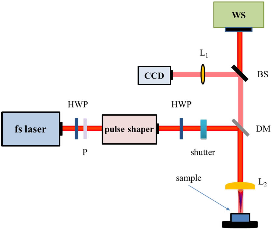
The schematic of the experimental setup is shown in Fig. 1. A commercial chirped Ti:sapphire laser regenerative oscillator–amplifier system (Spectra-Physics, Inc.) provided a fundamental Gaussian mode with a central wavelength of 800 nm, a pulse duration of 35 fs, and a repetition rate of 1 kHz. A half-wave plate (HWP) and polarizer combination was mounted for controlling the total energy of the pulse train. A fs pulse was shaped into a double pulse by a commercial 4f-configuration-based pulse shaper (Biophotonic Solutions Inc., MIIPSBOX 640), and the pulse delay could range from 0 to 5 ps. The polarization orientation of the incident laser pulses could be continuously adjusted by another HWP. The one-side-polished nickel sample () was mounted on a computer-controlled, 6-axis moving stage (M-840.5DG, PI, Inc.). A normally incident laser beam was focused onto the metal targets by a spherical lens with a focal length of 100 mm. The diameter of the Gaussian beam (width at the waist defined by point) on the sample surface was measured as about 45 μm by using Liu’s method[24]. All experiments were carried out in air at ambient pressure and temperature. The irradiated surface of nickel was examined by a scanning electron microscope (SEM) and an atomic force microscope (AFM).

Figure 1.Schematic of the experimental setup. BS, beam splitter; DM, dichroic mirror; , achromatic doublet; , plano-convex lens; P, polarizer; WS, white-light source.
In the first set of experiments, we study the effects of the scanning speed and the laser fluence (average fluence) on the transition between LSFL and HSFL under a fs laser single-pulse train. Figures 2(a)–2(c) shows the morphology of LIPSS at different scanning speeds (). The corresponding pulse number () is calculated based on the scanning speed, the repetition rate (1 kHz), and the diameter of the Gaussian beam (45 μm). When (), LSFL appears on the surface with a period of about 600 nm, which is smaller than the wavelength of the incident laser as previously reported[25]. As the scanning speed decreases, new grooves gradually appear on the protuberances between two original grooves as shown in Fig. 2(b). When (), more new grooves occur, which implies the formation of HSFL [Fig. 2(c)]. The previously mentioned distinctive structure with a grating-splitting process is usually described as HSFL[26] or deep subwavelength grating (DSG)[27]. In order to better observe the morphology evolution from LSFL to HSFL, the details of the morphology measured by AFM are shown in Figs. 2(d)–2(g). Figures 2(d) and 2(f) presents AFM 3D images at 300 and 100 μm/s, respectively. The cross sectional profiles [Figs. 2(e) and 2(g)] provide a more evident distinction between LSFL and HSFL. Compared with Fig. 2(e), it is obvious that new grooves are generated on the protuberances of LSFL as the red arrows shown in Fig. 2(g), which reveals that the formation of HSFL results from the splitting of LSFL.
Figure 2.(a)–(c) SEM images of LIPSS on the surface of nickel at different scanning speeds. Scale bars, 2 μm; (d) and (f) high-magnification AFM 3D images at and 100 μm/s; (e) and (g) cross sectional profiles for (d) and (f). Laser fluence, fixed at . AFM scanning area, . Scanning direction and polarization orientation are both horizontal.
To understand the combined influence of the scanning speed and the laser fluence on the transition between LSFL and HSFL, a series of experiments have been conducted by changing the previously mentioned processing parameters. Figure 3 presents the transition boundary of LIPSS morphology at different scanning speeds and laser fluences. From Fig. 3, it is distinct that the transition between LSFL and HSFL highly depends on the scanning speed and the laser fluence. When , the transition occurs within the laser fluence ranges from 0.1 to . Besides, it is noteworthy that the transition no longer occurs when the laser fluence exceeds . This unusual phenomenon can be explained by the high-density plasma under high fluence, which makes the laser energy highly localized in the grooves by the strong coupling of the incident laser and surface plasmons[28].
Figure 3.Transition boundary of LIPSS morphology on the surface of nickel with respect to the scanning speed and the laser fluence. Parameters for the SEM images, inset, of HSFL and LSFL are and 150 μm/s, and and 400 μm/s, respectively. Scale bars, 2 μm.
The previously mentioned results suggest a kind of formation process of HSFL on nickel surface. The changed reflectivity and field intensity distribution with groove depth are supposed to be main reasons for this splitting phenomenon. Moreover, as the excitation of surface plasmon is demonstrated under laser ablation of metal[25,29], the complex surface plasmon evolution can also be responsible for the morphology transition on the surface of nickel.
Apart from the scanning speed and the laser fluence, the laser polarization orientation is another significant parameter to control the morphology of LIPSS. In order to quantitatively investigate the morphology of LIPSS, a parameter K is defined as the proportion of HSFL area in the overall LIPSS area. We first calculate the area of HSFL (the dashed line region) and the whole area of LIPSS (the solid line region). Then K is obtained by the HSFL area divided by the LIPSS area. A schematic diagram of the HSFL area and the LIPSS area is shown in Fig. 4. The experimental result in Fig. 4 is obtained under a fs laser dual-pulse train.
Figure 4.Schematic diagram of the HSFL area and the LIPSS area. Scanning direction and the polarization orientation are both horizontal. Processing parameters, , 100 μm/s, and 300 fs pulse delay, respectively. Scale bar, 5 μm.
Figure 5 illustrates the influence of the polarization orientation on LIPSS morphology. The scanning direction remains horizontal, and a parameter is defined as the angle between the scanning direction and the polarization orientation as shown in Fig. 5(d). Figures 5(a)–5(c) are selected partially magnified SEM images of LIPSS from the corresponding Points a–c in Fig. 5(e). It is clear that K presents a quasi-parabola-function dependence on and the chiral phenomenon is with the center at 45° [Fig. 5(e)]. Term K reaches its maximum when or 90°, while reaching its minimum when at different laser fluences. Furthermore, it should be noted that there exists a constant 30 nm deviation of HSFL’s period between (300 nm) and (270 nm). A similar phenomenon that the period of nanogratings decreases as increases has been reported with respect to semiconductors[30,31], and the previously mentioned polarization-dependent phenomenon can be explained by the change of the mutual orientation of the laser polarization and the pulse front tilt (PFT)[30] or a 3D interference mechanism between the electron plasma and the incident electric field[31]. Nevertheless, the almost complete transition from HSFL to LSFL around may be related to the change of the reflectivity of nickel and more studies are needed for the underlying mechanism.
Figure 5.(a)–(c) Partially magnified SEM images of the LIPSS at different on the surface of nickel. Scale bar, 2 μm; (d) schematic diagram of the direct scanning process; (e) K as a function of at different laser fluences. Scanning speed, fixed at 100 μm/s ().
Except for the parameters under a single-pulse train, the effects of the parameters under a dual-pulse train on LIPSS morphology are also investigated. In Fig. 6, K is calculated by the method shown in Fig. 4 and presents an obvious fluctuation dependence on the pulse delay (). Term K keeps fluctuating until , and when , K drops to zero, indicating that nearly no HSFL appears and the LIPSS presents in the form of LSFL. As far as we know, this intriguing phenomenon is first proposed in this Letter. From the previously mentioned results, we find that a dual-pulse train can effectively control the morphology of LIPSS in a fluctuating way by changing the pulse delay within the range of 0–2.5 ps. Besides, in view of the possible instability of pulse shaper and the interference of external factor, repeated experiments are conducted on nickel at different laser fluences and scanning speeds, and similar results are obtained.
Figure 6.K as a function of pulse delay on the surface of nickel. Total laser fluence of the dual-pulse train and the scanning speed, fixed at and 100 μm/s ().
In addition, the combined influence of the polarization orientation and the pulse delay on K under a dual-pulse train is studied as shown in Fig. 7. Compared with Fig. 5(e), K also presents a quasi-parabola function trend with at , 300 fs, and 1.6 ps in Fig. 7(a). However, when , 2.5, and 3 ps, K remains close to zero. The results reveal that the influence of the polarization orientation on the morphology of LIPSS is interrelated with the pulse delay. Figure 7(b) shows K as a function of pulse delay at different . It is obvious that K presents a gradually diminished fluctuation range by changing from 0° to 45°. At , the fluctuation phenomenon almost disappears, which means HSFL no longer appears. A similar trend can be acquired by changing from 90° to 45°, which means the fluctuation range highly depends on .
Figure 7.(a) K as a function of at different pulse delays; (b) K as a function of pulse delay at different . Total laser fluence of the dual-pulse train and the scanning speed, fixed at and 100 μm/s ().
We attribute the morphology control of LIPSS by a dual-pulse train to the following two reasons. The first reason is the field intensity redistributed by a dual-pulse train. From the AFM images [Figs. 2(e) and 2(g)], it is obvious that the morphology of the LSFL’s and HSFL’s cross section is distinctly different, especially the depth of the grooves. According to Ref. [26], the field intensity distribution strongly depends on the depth of the grooves, and the changed field intensity can lead to the creation of new grooves on the protuberances. Ionin et al. also demonstrated an optical feedback effect due to a nonlinear cumulative ripple dynamics driven by the related instantaneous surface optical patterns[32]. A dual-pulse train is considered as a feasible method to adjust the interaction process between laser pulses and materials, which can affect the energy deposition in the material and eventually alter the morphology of the structures[33,34]. Thus, we suggest that the fluctuation of K with the pulse delay results from the field intensity redistribution, which is caused by the changed depth of the grooves under a dual-pulse train. Moreover, it has been proven that the plasma frequency or carrier density can be responsible for the morphology control of LIPSS by theoretical calculation. Li et al. found an alike oscillation phenomenon dependent on pulse delay on semiconductors, which is closely related to the localized carrier density[35]. Hou et al. presented that the coupling of the incident laser and the surface plasmons induce the laser energy highly localizing in the grooves (high-density plasma) or on the protuberance (low-density plasma) under different plasma states, and then lead to the transition between LSFL and HSFL[28]. Hence, the plasma frequency or carrier density adjusted by a dual-pulse train may also result in the fluctuation phenomenon.
In conclusion, the effects of different parameters of fs laser on the morphology control of LIPSS are systematically studied. The acquired transition boundary between LSFL and HSFL is found to be interrelated with the scanning speed and the laser fluence under a fs laser single-pulse train. A quasi-parabola-function trend of K is observed by changing from 0° to 90°. Furthermore, for a dual-pulse train, K shows a distinct fluctuation region within the pulse delay ranging from 0 to 2.5 ps. The corresponding results reveal that the control of the laser polarization orientation under a dual-pulse train is ineffective at specific pulse delays, although the similar polarization-dependent phenomenon at certain pulse delays is in agreement with the observation from a single-pulse train. Besides, the peak value of the fluctuation shows a direct correlation with . However, more theoretical and experimental studies are required for further understanding of the mechanisms that lead to morphology control of LIPSS.
References
[1] A. Y. Vorobyev, V. S. Makin, C. Guo. J. Appl. Phys., 101, 034903(2007).
[2] X. Jia, Y. Yuan, D. Yang, T. Jia, Z. Sun. Chin. Opt. Lett., 12, 113203(2014).
[3] J. Wang, C. Guo. Appl. Phys. Lett., 87, 251914(2005).
[4] S. Höhm, A. Rosenfeld, J. Krüger, J. Bonse. J. Appl. Phys., 112, 014901(2012).
[5] F. Kong, Y. Jin, S. Liu, S. Chen, H. Guan, K. He, Y. Du, H. He. Chin. Opt. Lett., 11, 102302(2013).
[6] J. Li, S. Ho, M. Haque, P. Herman. Opt. Mater. Express, 2, 1562(2012).
[7] G. Li, J. Li, Y. Hu, C. Zhang, X. Li, J. Chu, W. Huang. Appl. Phys. A Mater. Sci. Process., 118, 1189(2015).
[8] H. Pan, F. Luo, G. Lin, Q. Zhao. Chin. Opt. Lett., 13, 031404(2015).
[9] B. Tan, K. Venkatakrishnan. J. Micromech. Microeng., 16, 1080(2006).
[10] J. Bonse, A. Rosenfeld, J. Krüger. J. Appl. Phys., 106, 104910(2009).
[11] M. Huang, F. Zhao, Y. Cheng, N. Xu, Z. Xu. ACS Nano, 3, 4062(2009).
[12] R. Wagner, J. Gottmann, A. Horn, E. W. Kreutz. Appl. Surf. Sci., 252, 8576(2006).
[13] J. Bonse, S. Höhm, A. Rosenfeld, J. Krüger. Appl. Phys. A Mater. Sci. Process., 110, 547(2013).
[14] L. Jiang, X. Shi, X. Li, Y. Yuan, C. Wang, Y. Lu. Opt. Express, 20, 21505(2012).
[15] A. Borowiec, H. K. Haugen. Appl. Phys. Lett., 82, 4462(2003).
[16] G. Miyaji, K. Miyazaki. Opt. Express, 16, 16265(2008).
[17] Y. Dong, P. Molian. Appl. Phys. Lett., 84, 10(2004).
[18] M. Hashida, Y. Ikuta, Y. Miyasaka, S. Tokita, S. Sakabe. Appl. Phys. Lett., 102, 174106(2013).
[19] L. Qi, K. Nishii, Y. Namba. Opt. Lett., 34, 1846(2009).
[20] J. Reif, O. Varlamova, S. Uhlig, S. Varlamov, M. Bestehorn. Appl. Phys. A Mater. Sci. Process., 117, 179(2014).
[21] W. Han, L. Jiang, X. Li, P. Liu, L. Xu, Y. Lu. Opt. Express, 21, 15505(2013).
[22] S. Höhm, A. Rosenfeld, J. Krüger, J. Bonse. Appl. Surf. Sci., 278, 7(2013).
[23] V. P. Korolkov, A. A. Ionin, S. I. Kudryashov, L. V. Seleznev, D. V. Sinitsyn, R. V. Samsonov, A. I. Masliy, A. Zh. Medvedev, B. G. Goldenberg. Quantum Electron., 41, 387(2011).
[24] J. M. Liu. Opt. Lett., 7, 196(1982).
[25] F. Garrelie, J. P. Colombier, F. Pigeon, S. Tonchev, N. Faure, M. Bounhalli, S. Reynaud, O. Parriaux. Opt. Express, 19, 9035(2011).
[26] J. W. Yao, C. Y. Zhang, H. Y. Liu, Q. F. Dai, L. J. Wu, S. Lan, A. V. Gopal, V. A. Trofimov, T. M. Lysak. Opt. Express, 20, 905(2012).
[27] M. Huang, Y. Cheng, F. Zhao, Z. Xu. Ann. Phys. S, 525, 74(2013).
[28] S. Hou, Y. Huo, P. Xiong, Y. Zhang, S. Zhang, T. Jia, Z. Sun, J. Qiu, Z. Xu. J. Phys. D Appl. Phys., 44, 505401(2011).
[29] M. A. Gubko, A. A. Ionin, S. I. Kudryashov, S. V. Makarov, A. A. Rudenko, L. V. Seleznev, D. V. Sinitsyn. JETP Lett., 97, 599(2013).
[30] F. T. Zhang, H. Zhang, G. P. Dong, J. R. Qiu. J. Opt. Soc. Am. B, 31, 860(2014).
[31] Y. Dai, G. Wu, X. Lin, G. Ma, J. Qiu. Opt. Express, 20, 18072(2012).
[32] A. A. Ionin, S. I. Kudryashov, S. V. Makarov, A. A. Rudenko, L. V. Seleznev, D. V. Sinitsyn, V. I. Emel’yanov. Laser Phys. Lett., 12, 025902(2015).
[33] C. M. Liebig, P. Srisungsitthisunti, A. M. Weiner, X. Xu. Appl. Phys. A Mater. Sci. Process., 101, 487(2010).
[34] A. Klini, P. A. Loukakos, D. Gray, A. Manousaki, C. Fotakis. Opt. Express, 16, 11300(2008).
[35] X. Li, C. Li, L. Jiang, X. Shi, N. Zhang, Y. Lu. Opt. Lett., 39, 2382(2014).