1Key Laboratory of Materials for High Power Laser, Shanghai Institute of Optics and Fine Mechanics, Chinese Academy of Sciences, Shanghai 201800, China
2University of Chinese Academy of Sciences, Beijing 100049, China
A large-mode-area neodymium-doped silicate photonic bandgap fiber was theoretically designed and experimentally demonstrated. The relative index step between the high-index rods and the background glass was ~0.5%, which is the lowest cladding index difference reported on rare-earth-doped all-solid photonic bandgap fibers to our knowledge. An output power of 3.6 W with a slope efficiency of 31% was obtained for a 100-cm-long fiber.
The power scaling of fiber lasers and amplifiers are limited by nonlinear effects and stimulation of higher-order modes (HOMs)[1–4], which can be efficiently mitigated by using fibers with large-mode-area (LMA) designs.
Many strategies have been suggested to scale the mode-field area of fibers, such as photonic crystal fibers (PCFs)[5,6], photonic bandgap fibers (PBGFs)[7–13], large-pitch fibers[14], chirally coupled-core (CCC) fibers[15], multi-trench fibers[16], and distributed modal filtering rod fibers[17]. Among them, LMA-PBGFs have drawn much attention in recent years. Compared with other designs, LMA-PBGFs show some of the best HOM suppression performances[2,9,11]. Besides, the cladding of these fibers is highly dispersive[2], which can be used to suppress undesired amplified spontaneous emission (ASE)[18–22] and stimulated Raman scattering[23].
The cladding of PBGFs consists of high-index inclusions embedded in a low-index background. High-index contrast had been assumed to be a key to photonic bandgaps in early studies[24]. Calculations performed on two-dimensional lattices show that a relative index step (index difference/lower index) of over 160% is needed to generate bandgaps when light propagates perpendicular to the array of high-index rods[24]. However, theoretical studies on all-solid PBGFs (AS-PBGFs) present that when the longitudinal component is fixed but non-zero, photonic bandgaps can occur for much smaller index contrasts[25,26], and the bandgap formation mechanism has been discussed in this reference[26]. In 2004, the first, to the best of our knowledge, AS-PBGF was fabricated using silicate glasses with an index step of [27]. In the next demonstration in 2005, the refractive index of the high-index rods was only 1% above the background material[28], suggesting that photonic bandgaps can occur at arbitrarily weak index contrast.
Sign up for Chinese Optics Letters TOC. Get the latest issue of Chinese Optics Letters delivered right to you!Sign up now
Although light guidance based on photonic bandgaps at low-index contrast have been demonstrated by passive AS-PBGFs[27,28], cladding with low-index difference will lead to shallow bandgaps[29], thus decreasing the effective numerical aperture (NA) of the fiber core[30]. To our knowledge, the rare-earth-doped AS-PBGFs with low-index contrast have not been well studied, and it is not known whether laser emission can be generated in such fibers. By decreasing the cladding index contrast, the diameters of the core and the inner cladding can be scaled.
In this Letter, we demonstrate a single-mode Nd-doped AS-PBGF with an core diameter. The relative index step between the high-index rods and the background material is only 0.5%, which is the lowest cladding index difference reported on active AS-PBGFs to our knowledge. An output power of 3.6 W with a slope efficiency of 31% is obtained for a 100-cm-long fiber.
Four kinds of glasses were used to fabricate the fiber: the N0312 glass with an Nd doping level of 1.2 wt. %, and the undoped G1, G2, and G3 glasses. The N0312 glass was prepared by our laboratory, and the G1, G2, and G3 glasses were commercial silicate glasses provided by CDGM Glass Co. Ltd. The host compositions of the glasses are , and their thermal properties are shown in Table 1. The refractive indices of the N0312, G1, G2, and G3 glasses at 1064 nm are 1.5122, 1.5123, 1.5197, and 1.4614, respectively, measured by the V prism method with an accuracy of .
The single-mode performance of the fiber can be modified by two parameters: the diameter of the high-index rod , and the pitch of the fiber . The diameter of the high-index rod was calculated with Eq. (1): where is the normalized frequency[7–9,13] of the step-index fiber, which consists of the high-index rod and the background glass, and and are the refractive indices of the high-index rods and the background glass, respectively. The normalized frequency was set to be 4.65 in this study, which lies near the center frequency of the third bandgap[2,8,13,31]. The calculated diameter of the high-index rod was 10.5 μm.
The pitch of the fiber was determined by the overlap factor (OF)[13,17,32–36] of the fundamental mode (FM) and the high-order modes. Previous references show that in active fibers if the OF difference () between the FM and all HOMs is greater than 30%[13,17,32–35], a single-mode laser output can be obtained. The OF can be calculated with Eq. (2): where and are the areas of the doped core and pump region, respectively, and is the electric-field intensity of each calculated mode.
The confinement loss (CL) and of each guided mode in a straight fiber were calculated with the commercial finite difference time domain software MODE Solutions (v6.6.0, Lumerical Corp.). The anisotropic perfectly matched layer (PML) was used for the boundary condition. More than the first 50 guided modes were calculated to find the HOM with the largest OF (). A value of 0.35 was adopted according to the simulations.
The fiber preform was prepared by the stack-and-draw technique. A G1 glass tube with inner diameter of 8.4 mm and outer diameter of 24 mm and a G2 glass rod with a diameter of 8.4 mm were fabricated. After being sonically cleaned with ethanol, the G1 tube and G2 rod were drawn into rods with 1 mm in diameter by the rod-in-tube method. In addition, a G1 rod and a G3 rod with diameters of 24 mm were also fabricated and drawn into 1 mm diameter rods. The fiber preform was obtained by arranging the thin rods according to the designed structure, and then it was fed into the fiber fabrication tower. The target diameter of the fiber was .
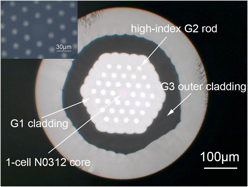
Figure 1 shows the cross-section of the fabricated fiber. The fiber core is composed by the N0312 glass. The gray background glass and the white high-index rods are fabricated by the G1 and G2 glasses. The low-index G3 glass serves as the outer cladding, and the G1 glass is used to be the jacket of the fiber. This fiber has a core diameter of with a value of , and the measured diameter of the high-index rod is . The NA and diameter of the inner cladding are and , respectively. The refractive index of the inner cladding is a little higher than that of the core, which will benefit the single-mode properties of the fiber[37]. It is worth noting that, as the inset of Fig. 1 displays, several small hollows are distributed along the inner cladding of the fiber, which will lead to the decrease of both the highest laser output power and the slope efficiency, according to our previous experiences. These air holes can be exhausted with an air pump during the fabrication process, but this solution is limited by our current experiment condition.
Figure 1.Cross-section of the fabricated fiber. Inset: magnified image of inner cladding.
Figure 2 presents the mode patterns of the FM in Fig. 2(a) and the in Fig. 2(b). The OF and CL of the FM are 58.13% and 0.01 dB/m, respectively, and the OF and CL of are 12.35% and 221 dB/m. The is greater than 30%, which guarantees single-mode transmission of the designed fiber.
Figure 2.Mode patterns of (a) FM and (b) . The OFs of the FM and the are 58.13% and 12.35%, respectively. The CLs of the FM and the are 0.01 dB/m and 221 dB/m.
We used a 100-cm-long fiber to build the laser. The fiber was cladding pumped with a commercial fiber-coupled laser diode operating at 804 nm. The pumping laser beam was aligned by a collimating lens with an NA of 0.25 and then focused and coupled into the fiber inner cladding through another aspherical lens with an NA of 0.3. The cavity consisted a butt-coupled dichroic mirror with 99% refractivity at 1064 nm and a perpendicularly cleaved fiber end with Fresnel reflectivity. The intrinsic loss of the doped core was [13,32,38], and the pumping absorption coefficient was measured by the cut-back method.
Figure 3 displays the laser performance of the fiber. The maximum power of 3.6 W is extracted from a 100-cm-long fiber with a slope efficiency of . No rollover is observed at the highest pump power, indicating that the maximum output power is limited by the pump power available. By eliminating the hollows with the proper fiber fabrication technique, higher laser output power and slope efficiency can be expected. The fiber laser spectrum is shown in the inset of this figure, which presents the center wavelength of the output laser is at .
Figure 3.Measured output power as a function of the absorbed pumping power. Inset: fiber laser spectrum.
The beam quality () factor at 3.6 W is shown in Fig. 4, which was measured by the Thorlabs BP109-IR2 beam profiler. The values at and orientations are 1.13 and 1.12, respectively. Considering the noncircular pattern of the FM, an factor of less than 1.2 can demonstrate the robust single-mode performance of this fiber.
Figure 4.Measured factor of the bandgap fiber. Inset: beam pattern in the far-field.
In summary, we have theoretically designed and experimentally realized an Nd-doped LMA-AS-PBGF with an active core diameter of . The relative index step between the high-index rods and the background material is only 0.5%, which suggests laser emission can be generated at an arbitrarily weak index contrast in rare-earth-doped AS-PBGFs. A laser output of 3.6 W with a slope efficiency of 31% is obtained for a 100-cm-long fiber. By eliminating the undesired hollows with the proper fiber fabrication technique, the laser performance can be further increased.