1College of Materials Science and Engineering, China JiLiang Universiy, Hangzhou 310018, China
2Key Laboratory of Space Laser Communication and Detection Technology, Shanghai Institute of Optics and Fine Mechanics, Chinese Academy of Sciences, Shanghai 201800, China
An efficient two-stage optical parametric amplifier (OPA) system with walk-off-compensating alignment is designed. By introducing an extra time delay between the pump pulse and the signal pulse, this OPA architecture is capable of obtaining high optical conversion efficiency and high signal gain simultaneously. Finally, a maximum gain of 98 at the 1.57 μm wavelength is obtained with the signal beam quality of around 5.6. The efficiency of the optical conversion from 1.064 to 1.57 μm is around 26%.
High-peak power, nanosecond-pulse, eye-safe (1.5–1.6 μm wavelength) laser sources are indispensable transmitters in different kinds of applications, such as air pollution detection, communications, range finders, remote sensing, and target indicators. Optical parametric oscillator (OPO) and optical parametric amplifier (OPA) architectures based on potassium titanyl arsenate (KTA) or potassium titanyl phosphate are the most effective methods for obtaining high-energy, eye-safe laser pulses, and till now, lots of significant progress has been made[1–7]. In 2004, by shaping the pump beam for an optimum spatial profile with a series of optical elements, Armstrong and Smith demonstrated a nanosecond KTA OPO with 170 mJ pulse energy output at 1550 nm. The beam quality () was 4[8]. In 2012, Foltynowicz and Wojcik demonstrated a maximum energy output of 243 mJ per pulse at 1535.2 nm from a KTA OPO system pumped by a -switched 1064 nm laser, but the beam quality () of the amplified signal was approximately 29[9]. Although the output energy from an OPO can be scaled to several hundred millijoules, it is quite difficult for a nanosecond OPO to obtain high gain, high efficiency, and good beam quality simultaneously in a simple and compact architecture. In order to further increase the signal pulse energy with good beam quality, a multi-stage, large-aperture OPA system is usually employed[7]. In an OPA system applied to a nanosecond pulse, the pump-pulse intensity distribution in the time domain is typically a Gaussian distribution. Generally, the signal gain of an OPA is directly proportional to the pump-pulse intensity; once the intensity distribution of the pump pulse is non-uniform, the signal gain coefficient of the OPA cannot keep a constant within the whole pump period. This kind of signal gain variation over time tends to result in an intensity depression in the central part of pump-pulse trace. Even more, if the signal gain within the low-intensity edges of the pump pulse is increased to a high level, serious back conversion will occur. Therefore, the temporal overlap of the pump pulse and the seeded signal pulse inside the OPA crystals need to trade-off well. The variation of the temporal overlap could improve the performance of OPA systems, although its details are ambiguous[10,11]. To obtain a better understanding of the principle, the details need to be analyzed.
KTA crystals have been used in OPA systems to obtain a wavelength 1.57 μm[12]. In this Letter, an optimum two-stage KTA-OPA configuration is determined in an experiment by adjusting the temporal overlap of the pump pulse and the signal pulse. The central depression phenomenon is eliminated by setting a suitable delay between the long pump pulse and the short signal pulse, so that no back conversion is observed. The experimental results reveal that time delay is a simple but effective method to achieved high conversion efficiency and good beam quality.
Referring to Refs. [13–15], a time-dependent model of three-wave mixing numerically integrates the following coupled differential equations[16]: where , , and are the amplitudes of the electric fields of the signal, idler, and pump pulses, respectively, () is the refractive index, () is the angular frequency, is the effective nonlinearity of the crystal, and is the phase-mismatching factor.
Sign up for Chinese Optics Letters TOC. Get the latest issue of Chinese Optics Letters delivered right to you!Sign up now
The model describes the stepwise time evolution of each beam on a two-dimensional spatial grid of intensity. Gaussian spatial profiles for the three beams are assumed. The walk-off effect is not included in this model, and the phase-mismatching value, , is assumed to be zero. A fourth-order Runge–Kutta algorithm is employed to numerically solve the above equations and to evaluate the pump-to-signal energy conversion efficiency, gain, and temporospatial profiles of the interacting pulses[17]. In our experiments, a 74.5° cut KTA crystal with type-II phase matching is used to amplify the seeded signal pulse of 1 mJ at the 1572 nm wavelength, which is pumped by a single-frequency -switched laser with a pulse energy around 400 mJ at 1064 nm. Both the pump beam and the signal beam have the same waist size of 4.5 mm inside the KTA crystals. The signal and the pump pulses are Gaussian in time, with 5.6 and 10 ns pulse widths, respectively. Our typical calculations are carried out with time interval of 0.2 ns in the numerical integration within the pulse duration. For the nanosecond pulses, the effects of the group-velocity mismatch among the pump, signal, and idler pulses are small and can be neglected in the numerical analysis.
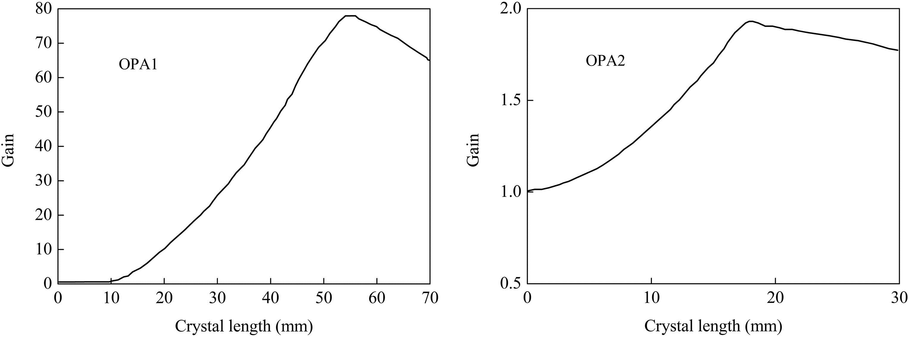
A two-stage OPA is designed based on the value of the temporal duration ratio of the pump to the seeded signal pulse, such as . In the OPA1 stage, the seeded signal first interacts with the falling parts of the pump. After the OPA1 stage, the pump is delayed by the delay line and the signal then interacts with the rising part of the pump. Therefore, whole portions of the pump pulse can be efficiently converted into the signal pulse by the OPA1 and OPA2 stages, resulting in high pump-to-signal conversion efficiency and gain simultaneously. For both of the OPA stages, the total length of the KTA crystal should be optimized because of the presence of back conversion. Figure 1 shows the theoretical calculation of the signal gain as a function of the crystal length for the two-stage KTA OPAs. In the OPA1 stage, the maximum gain occurs near the position at the crystal length of 55 mm, and the corresponding pump-to-signal conversion efficiency is about 18.7%. After the OPA1 stage, the pump pulse is time delayed by 2 ns, and the optimized length of the KTA in the OPA2 stage for obtaining maximum gain is around 18 mm. However, we only have two lengths for the KTA crystal, 20 and 15 mm, so in the OPA2 stage, a 15 mm KTA is used. Additionally, the walk-off effect induced by the nonlinear crystal should be compensated with pairs of KTA crystals[18]. Finally, two pairs of KTA crystals with dimensions of in the OPA1 stage and 15 mm in the OPA2 stage are applied in the whole OPA system. The overall energy conversion efficiency of 32% from the pump to the signal is expected.
Figure 1.Signal gain as a function of the crystal length.
Figure 2 shows the layout of our two-stage KTA-OPA experimental system. The whole OPA system was pumped by a home-built, -switched, single-longitudinal-mode Nd:YAG laser, which can deliver a 1064 nm laser pulse with about 400 mJ at a 100 Hz repetition rate. The pump beam quality of the OPA crystals was measured to be around 3.4. The OPO was a flat–flat resonator composed of a single 20 mm-long KTA crystal cut with for type II (o-eo) phase matching, so that stable lasing at the 1572 nm wavelength can be built. The pulse width of the signal wave from this OPO was approximately 5.6 ns. The signal pulse energy was limited to 1 mJ.
Figure 2.Experimental setup of the KTA-OPA system.
The OPA system was composed of four KTA crystals that were oriented for walk-off compensation. Two 20 mm-long crystals and one 15 mm-long crystal were lined up in the OPA1 stage. One 15 mm-long KTA was set up in the OPA2 stage. The pump path from the Nd:YAG laser to the OPA1 stage was 75 cm longer than that of the OPO to compensate for the buildup time of the signal pulse lasing in the OPO. Since the pump pulse went ahead of the signal pulse in the OPA1 stage, the falling part of the pump pulse was overlapped by the peak of the signal pulse. After the OPA1 stage, the idler wave was isolated to avoid serious back conversion in the OPA2 stage. In addition, the depleted pump pulse was delayed by an extra optical path of 45 cm in length, as shown in Fig. 2. The whole setup was constructed in accordance with the simulation results. The pump beam radius was set to 4.5 mm using a telescope, and only 375 mJ of energy was available to pump the KTA-OPA system.
Figure 3(a) shows the temporal evolution of the pump pulse; the falling parts and the rising parts of the pump pulse are clearly depleted. The total pump-pulse energy depletion for this two-stage OPA system was approximately 35%. Figure 3(b) shows the amplified signal pulse energy from this OPA alignment versus the crystal length in the experiments. The approximately exponential shape of the curve (even in the regime of large optical conversion) agreed with the expected results. Finally, with a 1 mJ signal pulse input, a maximum OPA signal pulse energy of 98 mJ (average power 9.8 W) was achieved on the condition of 375 mJ incident pump pulse, and the optical conversion efficiency was 26%. In addition, if the delay line of the pump pulse was removed, only 75 mJ of the OPA signal pulse could be detected, which was much smaller than that of the OPA system with the extra pump delay, as shown in Fig. 3(b). In order to further confirm that the pump delay was effective, another setup was verified. In this setup, the pump path from the Nd:YAG laser to the OPA1 stage was extended to 110 cm so the signal pulse was aligned to the peak of the pump pulse in the OPA1 stage. Also, the pump delay line between the OPA1 stage and the OPA2 stage was not setted. The temporal evolution of the pump pulse of the whole setup was tested. As shown in Fig. 4, in the OPA1 stage, a larger pump depletion could be obtaind in the peak-to-peak overlapping arrangement. However, serious back conversion happened in the OPA2 stage that lowered the overall conversion efficiency. So, we can come to the conclusion that the pump delay setting was helpful in improving the gain and efficiency of the OPA system.
Figure 3.(a) Pump profiles after the OPA1 and OPA2 stages. (b) Signal pulse energy increasing with crystal length.
The signal pulse profiles of the OPO and OPAs are shown in Fig. 5(a); no change in pulse duration was observed. After amplification by the OPAs, the falling part of the signal pulse was steeper. The beam quality of the amplified signal from this OPA system was determined by using an InGaAs camera equipped with a lens whose focal length was . Figure 4 shows the measured waists of the OPA signal beams at the output energy of 98 mJ. The beam quality of the signal pulses from the OPO was and . The beam quality of the signal pulses amplified by the two-stage OPA system decayed to a value of and , as shown in Fig. 3(b). Compared with the results reported by Arisholm et al.[7], the signal beam quality deteriorated too much in this OPA system. The reason for the serious deterioration of the signal beam quality is believed to be rooted in the non-uniform intensity distribution of the pump beam[19]. Furthermore, the signal beam quality of the OPA without pump delay is also measured, as shown in 5(b). The results reveal that the OPA configuration with the pump delay is capable of obtaining a better beam quality.
Figure 5.(a) Signal pulse profiles of OPO and OPA. (b) The measured waist variation of the OPA signal beam.
In conclusion, an efficient two-stage OPA system with pairs of phase-matching KTA crystals is constructed by introducing an extra time delay between the pump pulse and the signal pulse. With an extra delay design of the pump pulse, a total conversion efficiency of 26%, as well as the signal beam quality of and , are obtained.