1School of Physics and Electronics, Hunan Normal University, Changsha 410081, China
2International Collaborative Laboratory of 2D Materials for Optoelectronic Science & Technology of Ministry of Education, College of Optoelectronic Engineering, Shenzhen University, Shenzhen 518060, China
3Jiangsu Key Laboratory of Advanced Laser Materials and Devices, School of Physics and Electronic Engineering, Jiangsu Normal University, Xuzhou 221116, China
In this Letter, we have shown that a giant Goos–H nchen shift of a light beam reflected at terahertz frequencies can be achieved by using a composite structure, where monolayer graphene is coated on one-dimensional photonic crystals separated by a dielectric slab. This giant Goos–H nchen shift originates from the enhancement of the electrical field, owing to the excitation of optical Tamm states at the interface between the graphene and one-dimensional photonic crystal. It is shown that the Goos–H nchen shift in this structure can be significantly enlarged negatively and can be switched from negative to positive due to the tunability of graphene’s conductivity. Moreover, the Goos–H nchen shift of the proposed structure is sensitive to the relaxation time of graphene and the thickness of the top layer, making this structure a good candidate for a dynamic tunable optical shift device in the terahertz regime.
The Goos–Hänchen (GH) shift is a classical optical phenomenon that occurs when a light beam is reflected at the interface[1–3]. It has received researchers’ constant attention due to its wide applications in all optical switches[4], sensors[5,6], filters[7], and rainbow trapping[8]. While paying attention to the inherent physics of this phenomenon[9–11], researchers have also studied the GH shift in various materials and structures, such as yttrium-iron-garnet film[12], photonic crystals[13], weakly absorbing dielectrics[14], metamaterials[15], quantum wells[16], and metasurfaces[17]. The experimental observations of the GH shift have also been reported. Chen et al. have observed positive and negative lateral shifts in symmetrical metal-cladding waveguides[18]. Li et al. have observed giant GH shifts in total internal reflection conditions based on the beam splitter scanning method as well[19]. In addition, the GH shift under various mechanisms has also received extensive attention in order to obtain enhanced GH shifts, such as Fano resonance[20], surface plasmon resonance[21], plasmon-induced transparency[22], and guided mode resonance[23]. A common feature of these approaches is that the strong phase transitions are realized near the resonance angle by various kinds of resonance excitation, thus creating the conditions for achieving a large GH shift. It is predictable that the realization of tunable and enhanced GH shifts in new mechanisms, new materials, and new structures would remain the research focus in this field.
Graphene is a two-dimensional crystalline material consisting of monolayer carbon atoms. Owing to its specific characteristics, it has been caught in the spotlight of attention in the fields of physics, electronics, chemistry, and so on[24–28]. Specifically, in the fields of optics, graphene shows great advantages in realizing enhanced and tunable GH shifts due to its excellent properties, like dynamic control of electrical conductivity[29], zero band gap[30], and strong interaction with light waves[31]. Various structures based on graphene to obtain an enhanced GH shift have been reported, such as photonic crystal structure[32], attenuated total reflection configuration[33], metamaterials[34,35], and graphene-coated surfaces[36–38]. Therefore, it is very feasible to realize the enhanced and tunable GH shift in graphene-based micro-/nano-structures.
Recently, a Tamm plasmon, a surface wave confined at the interface of two different media, has also attracted wide attention because of its excellent characteristics. For example, it can be easily excited and has strong locality to light[39,40]. In comparison to a traditional surface wave, both a TM polarized wave and a TE polarized wave[41] can realize the excitation of optical Tamm states (OTSs) without requiring a particular incident angle. Thus, it is more flexible to realize the enhanced GH shift by exciting OTSs. It is well known that the traditional excitation of OTSs is mainly based on metal distributed Bragg reflector (DBR) construction[42]. However, graphene is intrinsically a semimetal with some similar metallic properties under certain conditions[43]. Therefore, graphene-based Bragg reflectors can also be used to excite the OTSs[44]. So, an interesting question arises: is it possible to achieve a tunable and enhanced GH shift by exciting OTSs through a graphene-based photonic crystal structure? To answer this question, in this Letter, we theoretically investigated the GH shift in the terahertz (THz) band in modified DBR construction. It is found that graphene-based OTSs can be used to realize giant GH shifts, and the giant GH shift originates from the localized abrupt phase change caused by the exciting of OTSs. Besides, the tunability of graphene conductivity created the condition for a tunable GH shift based on this structure. A normalized GH shift of orders of magnitude is achieved in this structure. It is also found that the values and signs of the GH shift can be flexibly tuned by manipulating the conductivity and other structural parameters of graphene. Electrically tunable optical transversal devices based on graphene OTSs allow us to find potential applications in biosensors, optical switches, and other areas of photoelectric detection.
Sign up for Chinese Optics Letters TOC. Get the latest issue of Chinese Optics Letters delivered right to you!Sign up now
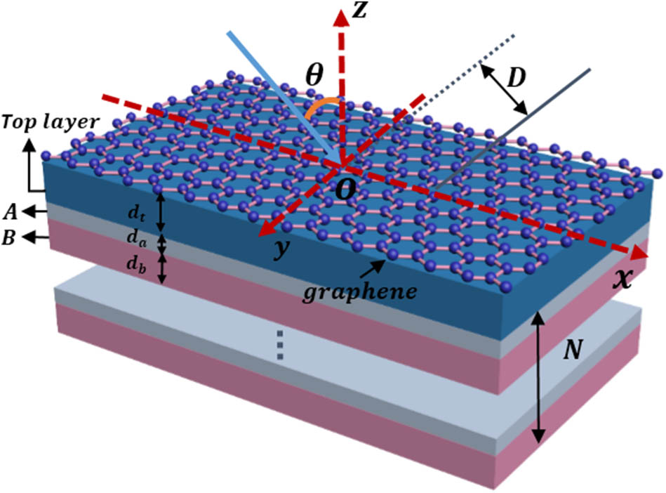
We consider a graphene one-dimensional photonic crystal (1DPC) structure. In this structure, a 1DPC is formed by alternately superposing dielectric layers A and B, whose refractive indices are and , respectively, and and represent the thicknesses of dielectrics A and B, respectively. A top layer with refractive index and thickness is placed above the 1DPC. Besides, the top layer is covered by monolayer graphene, as shown in Fig. 1. We call this structure a graphene Bragg reflector configuration (G-BRC), which is essentially a multilayer medium made up of graphene and a 1DPC. In this Letter, we selected the THz band and set the center wavelength as μ. The initial parameters of the G-BRC are set as , , and , where and , respectively, represent the refractive indices of polymethylpentene (TPX) and . For simplicity, the parameters of the top layer are set to be the same as dielectric layer B. Besides, surface conductivity is used to characterize the graphene within the local random phase approximation. The inter-conductivity of graphene is far less than the intra-conductivity of graphene, and thus the graphene conductivity can be approximately expressed as where and , respectively, represent charge and angular frequency, is the Fermi energy. We know that is closely related to carrier density : ( is the reduced Planck constant, is the Fermi velocity of electrons[45]). These relationships have created the condition for controlling conductivity through the gate voltage. In order to obtain the GH shift of the reflected beam on the structure surface, we need to calculate the reflection coefficient of the beam on the structure surface. As is known, the transmission matrix method is a classical numerical method for calculating the reflection and transmission coefficient of a one-dimensional multilayer structure. For the case of graphene embedded in the multilayer structure, the conductivity characteristics of graphene can be reflected in the boundary conditions[46]. In this Letter, we only consider the GH shift in the TM polarization; thus, the transmission matrix between the air layer and top layer can be expressed as where , , and , respectively, represent the wave vector components of the light wave in the direction of propagation of the air layer and the top layer. According to Eq. (2), the conductivity of graphene is reflected in the boundary conditions. Hence, we can ignore the thickness of graphene in the computation. Based on the propagation matrix ( is the thickness of the dielectric layer) of the light in the dielectric layer, the transfer matrix of the whole structure can be written as , where represents the period of the 1DPC. Therefore, the reflection coefficient of the whole structure can be expressed as , and the reflected phase of the configuration is further obtained. Based on the stationary phase method, for the incident beam with a sufficiently large beam waist, the GH shift of the reflected beam can be expressed as where represents the incident angle. Based on Eq. (3), we can easily calculate the GH shift of the G-BRC. In the following analysis, we set , , , and .
Figure 1.Schematic diagram of the GH shift of the reflected beams from the G-BRC. The incident and reflected beams are schematically represented by their respective beam axes.
Now, we discuss the characteristics of the GH shift in G-BRC. For the sake of simplicity, the loss of the dielectric layer is ignored. Based on the structural parameters set in the front section and according to Eq. (2), we plotted the reflection coefficient and reflectance of the G-BRC. The results are shown in Figs. 2(a) and 2(b). It can be found from Fig. 2(a) that the introduction of the graphene makes the OTSs excited. A remarkable dip of the reflectance appeared in the vicinity of 54°. The reflectance near the dip is not zero, albeit small. It is an obvious excited behavior of OTSs. Here, we represent the angle for exciting OTSs as . In essence, the structure shown in Fig. 1 can be regarded as a multilayer medium composed of graphene and 1DPC. Graphene can be regarded as a mirror on the left side of the system due to its metal-like properties. In fact, in the THz wave band, intra-conductivity of graphene becomes very large, which makes it a feasible “reflection mirror”. The 1DPC acts as the right mirror in the system by selecting appropriate structural parameters and periods to realize the photonic bandgap. It is well-known that the excitation of OTSs should satisfy , where is the reflection coefficient of the graphene surface in the top layer, is the reflection coefficient of the 1DPC surface in the top layer, and is the phase change of light wave transmission in the top layer. Based on the initial parameters set before, we can obtain and . These results are consistent with the previous condition. The normalized electric field distribution in Figs. 2(c) and 2(d) also confirms the excitation of OTSs. It can be seen from Fig. 2(d) that when OTSs are in the excitation state, the electric field energy is mainly localized near graphene. This is completely different from the electric field distribution without exciting OTSs. At the same time, the change of graphene conductivity affects the real and imaginary parts of the reflection coefficient. For example, the curves corresponding to and are shown in Fig. 2(b). When , although the dip exists in the real part of reflection coefficient, it always satisfies near . At the same time, the imaginary part of the reflection coefficient increases monotonously with the incidence angle around , and there is a zero point near . When , the minimum value of the real part of the reflection coefficient drops to below zero, but the imaginary part of the reflection coefficient still increases monotonously near , and its zero point is between the two zero points of the real part of the reflection coefficient, which provides an adequate explanation for the changing trend of the reflection phase with an angle. Figure 3 shows the relationship between the reflected phase of the G-BRC and the change of the GH shift with the incidence angle. We can see clearly that when , owing to , , , and , the reflected phase is monotonically increasing near , as shown in Fig. 3(a). In combination with the Eq. (3), the monotonically increasing reflection phase directly leads to the generation of the negative GH shift, and the normalized GH shift of can be obtained in the vicinity of . At the same time, with the proper decrease of Fermi energies, the GH shift will further decrease, and the normalized GH shift of can be amazingly obtained near . It can be seen that the excitation of OTSs will achieve an intense phase change near , and thus a condition of obtaining a large GH shift is created. However, in the above case, the GH shift will not decrease with Fermi energies. With the control of Fermi energies on the reflection coefficient of the structure, as it continues to decrease, the minimum value of the real part of the reflection coefficient will exceed the zero value, causing the reflection phase to appear as at and at . As a result, the reflection phase presents a monotonous decreasing trend near and is accompanied by the generation of positive GH shift. From Fig. 3(b), we can obtain the normalized GH shift of in the vicinity of . Figure 3(c) is the colored contour plot describing the relation of the reflection GH shift to and the incident angle. For convenience, GH shift values larger than 2000 and lower than −2000 were plotted in the same color. It can be seen from Fig. 3(c) that the largest GH shift appears on the corresponding angular position, where the minimal real part of the reflection coefficient approximates zero. Theoretically, GH values near this angle could reach both positive infinity and infinitesimal negatives. However, larger GH shift corresponds to narrower angular range, which is disadvantageous to our evaluation. Therefore, a proper deviation from the excitation angle of OTSs would be very useful in practical applications. The above results are very significant, which indicate that it is possible to achieve the giant, value, and sign dynamic tunable GH shift in G-BRC.
Figure 2.(a) Reflectance and (b) reflection coefficient as functions of incident angle at different Fermi energies for the TM polarized wave. The normalized electric field profile distributions in the G-BRC (c) without and (d) with the covering of graphene.
Figure 3.(a) Reflected phase and (b) reflected GH shift as functions of incident angle at different Fermi energies for the TM polarized wave. (c) Dependence of the reflected GH shift on the Fermi energy and the incident angle.
In the previous calculation of GH shift, the incident beam is assumed to be a well-collimated beam with sufficient width. Whether it is equally applicable to an incident beam with a finite width is a matter of great concern. In the following discussion, we will conduct further simulation to verify this point. We assumed that the Gaussian-shaped beam is incident on the surface of G-BRC, as shown in Fig. 1. At the plane of , the electric field expression of the incident beam can be expressed in integral form[47]: , where is the initial angular spectrum distribution of Gaussian beam, , , and is the half-width of the beam of incident plane. Meanwhile, the electric field of the reflected beam can be expressed as . Therefore, the lateral shift of the G-BRC can be expressed as Based on the above expression, we can get the lateral shift simulation value of the reflection beam on the G-BRC surface, as shown in Fig. 4. In order to approximate the theoretical calculations (Fig. 2) as closely as possible, the half-width of the beam is set as in Figs. 4(a) and 4(c), and the half-width of beam is set as in Fig. 4(b). From Fig. 4, it is found that when Fermi energies of graphene, respectively, satisfy and , the simulation gets a positive GH shift, and when the Fermi energy takes , the GH shift is negative. The situation is in accord with Fig. 2. Furthermore, when , the maximum of the GH shift at in Fig. 4(a) is ; the GH shift at the same angle in Fig. 2 is . These results are very close. Similarly, when the Fermi energies satisfy and , the maximum and minimum of the GH shift simulated at and in Figs. 4(b) and 4(c) are and ; the GH shifts calculated at the same angular position in Fig. 2 are and , respectively. The above results are also very close, which fully demonstrates that the GH shift results obtained from the stationary phase theory are also available for large finite width incident beams.
Figure 4.Numerical simulations of the reflected beam from the G-BRC under different Fermi energies. The red and blue curves denote the incident and reflected probe beams, respectively. Other parameters are the same as in Fig. 2.
From Eq. (1), we found that the key parameter manipulating the conductivity characteristics of graphene is the Fermi energy, which can directly control the conductivity of graphene by external voltage. However, we can also see that the relaxation time of graphene also has a very significant effect on the conductivity. Although it is hard to change the relaxation time of the graphene-related device once it is prepared, it is still necessary to systematically research the effect of the GH shift of the whole structure. Therefore, we also pay attention to the effect of different relaxation time of graphene on the GH shift of the G-BRC, as shown in Fig. 5. The Fermi energy of graphene is set as in the calculation of Fig. 5, and other parameters are consistent with Fig. 2. It is found that with the increase of the relaxation time of graphene, the zero point of the corresponding reflection phase tends to shift to a low angle. However, the overall deviation is small. This is mainly because the increase in relaxation time will strongly affect the real part of the conductivity of graphene, but its influence on the imaginary part of the conductivity of graphene seems very weak. Therefore, the influence on the zero position of the reflection phase is limited, and the regulatory effect is mainly reflected in the influence on GH amplitude. At the same time, the increase of relaxation time makes the reflection phase gradually jump from “the monotone increasing with the angle” to “the monotone decreasing with the angle”, thus realizing the transformation from the negative GH shift to the positive GH shift. In the amplitude of the GH shift, the peak value of the GH shift will also first increase and then decrease as the relaxation time increases. In general, compared with the influence of the change of Fermi energy on the GH shift, the change of relaxation time has a relatively mild effect on the lateral shift. However, relaxation time also provides a way to manipulate the GH shift at a certain incidence angle.
Figure 5.Dependences of the (a) reflected phase and (b) normalized GH shift on the incident angle at different relaxation times of graphene.
As we know, the top layer is very important to the excitation of OTSs, and its structural parameters will sensitively influence the excitation angle and excitation frequency of OTSs. Correspondingly, the structural parameters of the top layer should be equally sensitive to the GH shift of the G-BRC. Hence, it is very essential to further analyze the change of the structure parameters of the top layer to the law of the GH shift, and these laws will provide an important reference for the design of optical lateral shift devices. We have plotted the contour plot of the top layer thickness and dielectric constant on the GH shift at different angles within a certain range, as shown in Fig. 6. It is noteworthy that in order to facilitate the comparison and discover the law of the GH shift of the structural parameters, the normalized GH shift less than −200 is uniformly represented as blue in the colorful graph; the normalized GH shift over 200 is uniformly expressed as pure red. It can be seen from Fig. 6(a) that the increase in the thickness of the top layer causes to move to a higher angle, and the magnitude of the movement is severer than the influence of the graphene dispersion parameter. Meanwhile, the thickness of the top layer changes the sign and amplitude of the GH shift more than once during the gradual increase. When increases in a range smaller than 40.25 μm, the G-BRC shows a negative GH shift, which increases negatively with . However, once is greater than 40.25 μm and continues to increase, the GH shift would jump to a positive GH shift and present a process of positively decreasing first and then increasing with increasing thickness. When exceeds 43.75 μm, the GH shift will jump from positive to negative. of the top layer also has a similar phenomenon to . These phenomena have the same points but differ in the effect of the graphene dispersion parameter on the GH shift. Therefore, appropriate and are necessary for obtaining an enhanced GH shift and must be fully considered when designing the corresponding GH shift device.
Figure 6.(a) Reflected GH shift as a function of incident angle and for the G-BRC in Fig. 1. (b) Reflected GH shift as a function of incident angle and for the G-BRC. Other parameters are the same as in Fig. 2.
In this study, we have investigated the GH shift of a reflected beam based on the G-BRC within the framework of the transfer matrix method. The excitation of OTSs on the surface of graphene makes the change of the reflected phase extremely intense near the resonance angle, which greatly enhances the GH shift. Numerical calculations reveal that the maximum normalized GH shift can exceed 1000, and the minimum normalized GH could be less than through selecting the appropriate Fermi energy. The values and signs of the GH shift strongly depend on the conductivity properties of graphene and other structural parameters. This provides a new way to achieve electrically tunable GH shifts. The numerical simulation has also verified the correctness of the results in terms of finite beam width. We believe that the pathway of the enhanced and controllable GH shift investigated in this Letter can find potential applications in optical sensing, optical waveguide switches, and other related optical devices.