
Chaoxu Chen, Xiaomeng Zhou, Ziwei Li, Chao Shen, Junwen Zhang, Jianyang Shi, Nan Chi. Lens-free wavefront shaping method for a diffuse non-line-of-sight link in visible light communication[J]. Chinese Optics Letters, 2024, 22(2): 020603
- Chinese Optics Letters
- Vol. 22, Issue 2, 020603 (2024)
Abstract
1. Introduction
Visible light communication (VLC) is an emerging wireless technology that combines illumination and communication functions. Compared to traditional RF communication, VLC offers advantages such as high capacity, high speed, low latency, and low energy consumption, making it suitable for applications in the IoT, smart manufacturing, and multimedia sectors in the 6G era[1-6].
In the spatial transmission of visible light signals, direct links between transmitters and receivers are often obstructed by obstacles, which hinders effective communication[7-9]. In indoor scenarios, a common approach is to use diffuse materials like walls and ceilings as intermediate media for non-line-of-sight (NLOS) VLC links. However, when light beams pass through these diffuse media, their optical fields become chaotic due to interactions with microscopic particles and non-uniform refractive indices[10,11]. This results in phenomena such as light path deviation and beam divergence, causing the received light intensity to fall far below the minimum detectable threshold, leading to communication failures.
Wavefront shaping techniques based on liquid crystal spatial light modulators (SLMs) are commonly used to address this problem[12-14]. For static diffuse media, the paths of scattered light experienced by the beams are fixed. By compensating for the spatial phase distribution of the scattered field, the focus of the beam can be enhanced. The continuous sequence (CS) algorithm is widely employed for wavefront shaping, dividing SLM pixels into blocks and iteratively adjusting the phase magnitude of each block until the strongest optical power distribution is obtained[13]. However, in practical applications, this method requires the addition of a lens in front of the diffuse media to control the size of the incident beam for enhancing the algorithm’s performance[13,14].
Sign up for Chinese Optics Letters TOC. Get the latest issue of Chinese Optics Letters delivered right to you!Sign up now
In this Letter, we propose a lens-free wavefront shaping method utilizing synchronized signal block (SSB) beam alignment and genetic algorithm (GA) optimization (SSBGA) for a diffuse NLOS VLC system. Inspired by SSB beams in the 5G network[15], our proposed SSBGA can manage the position and mobility of visible light beams to increase the efficiency of wavefront shaping. By utilizing this approach, we achieve a performance improvement of 23.9 dB in received optical power at a horizontal offset of 2 mm, surpassing lens-based CS by 21.7 dB on a 1.2 m NLOS VLC experimental platform. At a 40° offset angle, a noteworthy improvement of 11.8 dB is demonstrated compared to lens-based CS, while the increase can amount to 16.8 dB compared to scenarios without optimization. Building upon this, we transmit discrete multi-tone (DMT) modulated signals using bit-power-loading techniques[16,17], achieving a maximum data rate of 5.16 Gbps under the hard decision-forward error correction (HD-FEC) threshold of . Under similar conditions, our solution outperforms lens-based CS by 1.07 Gbps and provides a 3.01 Gbps enhancement compared to the unoptimized state. Furthermore, our proposed SSBGA reduces the required transmission power for lens-based CS, resulting in a 55.6% power saving while achieving a 4 Gbps transmission rate. Our approach reduces the demand for transmission power during signal transmission, providing experimental and theoretical support for high-speed visible light communication in real-world NLOS scenarios.
2. Principle
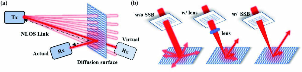
In 5G NR (New Radio) networks, SSB beams refer to signal blocks that are synchronized in terms of time, frequency, and phase. They play an important role in the positioning and mobility management of signals. Figure 1(a) illustrates the presence of a virtual Rx on the right side of the diffusion surface, while the one on the left is the actual target. The transmitter emits probing beams into the target space, and the alignment of these beams is achieved by using receiver feedback to determine their direction.
![]()
Figure 1.(a) SSB alignment; (b) focusing capacity of beams without SSB, with lens, and with SSB on the diffusion surface.
Our approach begins by scanning the power of the received light at different spatial positions using Fresnel lenses loaded on an SLM, in order to determine the position of the receiver. The phase distribution formula for Fresnel lenses is as follows[18,19]:
As shown in Fig. 1(b), when beams are not aligned using SSB, they quickly scatter, making it difficult for the receiver to receive meaningful information. Adding a lens can achieve some degree of focusing, but due to the fixed focal length and focusing position, strict alignment with the optical link is required. On the other hand, using SSB beams allows for the focusing of optical power based on the scanning position of the receiver. We conducted position searches on the SLM with configurations of , , and .
After completing the alignment mentioned above, as shown in Fig. 1(a), further optimization of the parameters of the Fresnel lens is required to achieve accurate focusing due to the presence of diffuse media. This can be done by employing a block-based optimization approach similar to CS methods. The SLM plane is divided into blocks, and the phase values are modified to suppress the effect of diffuse reflection. A GA is used to optimize these parameters and obtain the optimal wavefront phase distribution. The optimization objective and its constraints are defined as follows:
Here, represents the position of SSB alignment, represent phase values for each block, ranging from 0 to 255, corresponding to phase values from 0 to . represents the optimization range of the focal length of the Fresnel lens. The optimal spatial position is searched within of the pixel count in both horizontal and vertical directions of the blocks. The optimization objective is to maximize the optical power after SSB and perform GA for block-wise phase optimization[20]. The pseudocode of our method is as follows.
| SSB and GA joint optimization | |
| SSB | SSB blocks number: N × N |
| Focusing length from SLM to the diffusion surface: F | |
| get center coordinates of block i: (X,Y) | |
| calculate | |
| load | |
| load the best | |
| GA | Generation count: t = 0 Max generations: T |
| Population size: M Migration factor: | |
| Parameters size: N × N + 3 | |
| Generate M × (N × N + 3) random matrix V0 | |
| load each row of Vt on SLM and get optical power Pt rank Vt according to Pt | |
| | |
| generate binary vector K | |
| select the first and second rows v0 and v1 from Vt | |
| Vt+1(i) = v1 × K + v2 × (1 − K) | |
| | |
| | |
| if random < α | |
| Vt+1(j) = random | |
| | |
| Out | Phase vector: VT(1,:) and optical power: PT(1) |
For our method, the output is the first row of optimized matrix . The first three values of the vector correspond to the parameters of the Fresnel lens, which are loaded onto the SLM based on Eq. (1). Subsequently, the remaining phase values for each block are mapped onto the actual phase. The mapping method for the th block’s phase can be defined using the following formula:
Here, represents the phase distribution matrix of the SLM, where denotes the number of pixels in the horizontal direction of the SLM, which is 1920, and represents the number of pixels in the vertical direction of the SLM, which is 1200.
3. Experimental Setup
Figure 2 depicts the experimental setup of a 1.2 m NLOS VLC link used to validate this work. At the transmitter side, a signal generator with a maximum sampling rate of 4.2 GSa/s (Tektronix, AWG710B) is used to generate a DMT signal. The signal is amplified by an amplifier (Mini-Circuits, ZFL-2500VH+) and attenuated using an adjustable attenuator (SMA, KT3.0-30/1S-2S) to suppress nonlinearity. Then, it is coupled to a laser diode mount (Thorlabs, LDM9T/M), integrated with a thermoelectric cooler (TEC), and controlled by a controller. A 638 nm laser diode (Mitsubishi, ML501P73) is used to emit visible light signals.
![]()
Figure 2.Experimental setup.
The visible light signal passes through a polarizer after beam expansion to match the polarization state with the SLM (Meadowlark, XY Phase Series). The modulated light then enters a diffusion surface (Thorlabs, EDU-VS1/M). The scattered light is collected by a receiver, comprising a collimating lens and an avalanche photodiode (MenloSystems, APD210). The received signal goes through an amplifier and an attenuator, identical to those used at the transmitter, and is finally captured by an oscilloscope (Agilent Technologies, MSO9254A) for signal processing and iterative optimization on a computer. The working parameters during optimization are fixed, with a signal voltage (Vp-p) of 900 mV and bias current of 250 mA.
In the experiment, the SLM is used for SSBGA. During the SSB process, the pixels of the SLM are divided into , , or pixel blocks. A Fresnel lens is loaded at the center of each block and scanned to achieve alignment. In the GA process, the pixels are similarly divided into blocks, and besides optimizing the phase of the Fresnel lens after alignment, the phase values of the blocks vary from 0 to .
The receiver is mounted on a three-dimensional adjustment stand, allowing movement along the X-axis and angular offsets up to by rotating the diffuse reflection plate, altering the angle perpendicular to the experimental platform shown in Fig. 3.
![]()
Figure 3.Photo of the experimental platform.
Regarding signal processing, we transmit DMT signals as shown in Fig. 2, which involves two main parts: signal-to-noise ratio (SNR) estimation and bit-power loading. First, we transmit QPSK modulated signals to estimate the channel SNR. All subcarriers are mapped with QPSK symbols and then modulated using DMT. Based on the predetermined SNR table, the number of bits per DMT modulation subcarrier is calculated. Under a given power budget, while maintaining a 7% FEC error rate threshold (), we use the Levin–Campello (LC) algorithm to maximize the bit allocation for each subcarrier, achieving maximum spectral efficiency and data rate. At the receiver side, the received signal is demodulated, and the error rate is calculated.
4. Results
Figure 4 illustrates the SSB alignment process, comparing the alignment performance for different partitions. Figures 4(b), 4(c), and 4(d) show the power distribution and corresponding Fresnel lens holograms of alignment block schemes of , , and , respectively. It can be observed that as the block size increases, the search becomes more precise, resulting in higher obtained optical power. Additionally, Fig. 4(a) displays the distribution of the obtained optical powers with respect to the number of searches. Although the alignment scheme achieves the highest optical power, it requires significantly more search times compared to the and schemes. This implies that obtaining a more accurate alignment position would require sacrificing some time cost during the SSB process. However, as shown in Fig. 5(a), increasing the refinement level of the SSB division accelerates convergence speed in the GA process. This means that although fine-grained SSB alignment may add time cost during the SSB stage, it can expedite convergence in the GA process. In this case, the GA optimization is divided into blocks, with a population size of 50 and a migration factor of 0.5.
![]()
Figure 4.(a) Obtained optical power distribution after SSB alignment with respect to the number of searches. Performance comparison for different block divisions: (b) 4 × 4, (c) 8 × 8, and (d) 16 × 16.
![]()
Figure 5.Convergence curve for different (a) SSB schemes, (b) population sizes, and (c) migration factors.
After the SSB is completed, as shown in Fig. 6, GA is performed based on the aligned Fresnel phase. The GA schemes remain as , , and block partitions. The population size is set to 50, and the migration factor is set to 0.5. After 20 generations of GA, the final optical power achieved is very close for all schemes. Nevertheless, the scheme exhibits a relatively slower convergence speed compared to the and schemes with an equal number of generations. This phenomenon can be attributed to the increased number of parameters involved in the scheme. Since the Fresnel lens also participates in the GA process, the gain obtained from optimizing the Fresnel lens alone is lower (1.16 dB) than the gain achieved through joint optimization.
![]()
Figure 6.Convergence curve for different partition schemes in GA.
Next, we proceed to fine-tune the parameters of the GA. Figures 5(b) and 5(c) display the optimization results for the SSBGA. The use of a small population size in the algorithm can make it prone to converge to a local optimum, which, in turn, can adversely affect the final iteration results. The mutation probability determines the speed at which the algorithm escapes from a local optimum, but it can also impact the stability of the algorithm to some extent.
In Fig. 7, we compare SSBGA with the CS-only method and the lens-based CS algorithm. It can be observed that SSBGA achieves significantly better optimization results compared to the other two methods.
![]()
Figure 7.Comparison of optimization results among CS-only, lens-based CS, and SSBGA.
In Fig. 8, we present the variation of received optical power along the X-axis for different schemes. Due to the SSB alignment, our scheme exhibits lower sensitivity to position compared to the other schemes. At the central position, SSBGA achieves a gain of 19 dB compared to the original state, and still provides an 11.5 dB gain over the lens-based CS. For a 2 mm offset position, the gains elevate to 23.9 dB and 21.7 dB, respectively. Subfigures (i), (ii), (iii), and (iv) represent the optimized phase maps at , , , and degrees of offset positions, respectively, where the center position of the Fresnel lens varies with position.
![]()
Figure 8.Optical power along the X-axis for different schemes.
In Fig. 9, we show the variation of received optical power along the X-axis with different offset angles. After SSB alignment, the center position of the Fresnel lens slightly varies with different angles. SSBGA exhibits less attenuation in optical power compared to other schemes for smaller angles (), showing higher stability. However, for larger deflection angles, the gain is lower but still provides a 16.8 dB improvement compared to the original non-optimized state, and an 11.8 dB improvement over the lens-based CS.
![]()
Figure 9.Optical power along the X-axis with different offset angles.
We then compare the data rate of DMT signals for different schemes, as shown in Fig. 10. The best wavefront phases from each optimization scheme are loaded for comparison. In Fig. 10(a), with a bias current set to 300 mA, the data rate follows a trend of initially increasing and then decreasing with signal voltage. This trend is particularly evident in SSBGA and the lens-based CS. The AM-AM curves for a 1400 mV signal voltage are shown in subfigures (i) to (iv). It can be observed that the decrease in rates for SSBGA and lens-based CS is due to nonlinearity caused by receiver optical saturation. SSBGA demonstrates the best alignment performance and gain, entering the nonlinear region earlier than the other schemes. Both the non-optimized state and the CS-only optimized scheme have not yet reached saturation. However, they exhibit a wider central distribution in terms of AM-AM, which indicates a lower SNR. SSBGA achieves a maximum data rate of 5.16 Gbit/s at 1000 mV, saving 640 mV of waveform voltage compared to the lens-based CS and reducing power consumption by 55.6% when reaching a transmission rate of 4 Gbps. In Fig. 10(b), we observe that the data rate increases and then decreases as the bias current varies for all schemes. Compared to the original non-optimized state, our scheme achieves a maximum rate improvement of 3.01 Gbps, and an improvement of 1.07 Gbps over the lens-based CS at the optimum waveform voltage.
![]()
Figure 10.(a) Data rate comparison for different schemes with varying signal voltage; (b) data rate variation with bias current for different schemes at the optimum waveform voltage.
5. Conclusion
We have proposed a lens-free wavefront shaping scheme using SSB beam alignment for NLOS VLC links, achieving focusing of visible light scattered by diffuse media. Our proposed SSBGA aligns the receiver in unknown positions within NLOS space through scanning, eliminating the need for a lens in the visible light link, which is more practical compared to traditional methods. However, this method in the SSB stage requires excessive computation time. Therefore, it is advisable to employ optimization algorithms to minimize the computational burden. Moreover, compared to the lens-based CS, our scheme achieves higher gains. By employing the SSB alignment scheme, our solution demonstrates stability within horizontal displacement. At an offset position of , we achieve a significant optical intensity improvement of 23.9 dB, far surpassing the gain of 2.2 dB achieved with the lens-based CS scheme. Additionally, in terms of angular deviation, at a large angle position of , our scheme outperforms both the lens-based CS scheme and the unoptimized scheme with improvements of 11.8 dB and 16.8 dB, respectively. Under the DMT signal, our scheme achieves a maximum data rate of 5.16 Gbps on the current experimental platform. This represents an improvement of 1.07 Gbps over the lens-based CS scheme and 3.01 Gbps over the original unoptimized state. For a target transmission rate of 4 Gbps, our scheme saves 55.6% of power compared to the lens-based CS scheme. To the best of our knowledge, this represents the pioneering achievement of high-speed communication in an NLOS VLC system, accomplished without the use of a lens. These results substantiate the feasibility and practicality of employing the SSBGA approach in real NLOS visible light communication scenarios.
References
[1] N. Chi. LED-Based Visible Light Communications(2018).
[2] H. Haas. Visible light communication. Optical Fiber Communications Conference and Exhibition (OFC), 1(2015).
[4] M. Katz, I. Ahmed. Opportunities and challenges for visible light communications in 6G. 2nd 6G Wireless Summit (6G SUMMIT), 1(2020).
[8] C. Chen, D. Basnayaka, H. Haas. Non-line-of-sight channel impulse response characterisation in visible light communications. IEEE International Conference on Communications (ICC), 1(2016).
[10] D. Faccio, A. Velten, G. Wetzstein. Non-line-of-sight imaging. Nat. Rev. Phys., 2, 318(2020).
[15] Z. Lin, J. Li, Y. Zheng et al. SS/PBCH block design in 5G new radio (NR). IEEE Globecom Workshops, 1(2018).

Set citation alerts for the article
Please enter your email address
© Copyright 2018-2021 | Chinese Laser Press. All Rights Reserved 沪ICP备15018463号-20