Shanghai Institute for Advanced Communication and Data Science, State Key Laboratory of Advanced Optical Communication Systems and Networks, Department of Electronic Engineering, Shanghai Jiao Tong University, Shanghai 200240, China
Zhengpeng Shao, Kan Wu, Jianping Chen. All-optical inverter based on carbon nanotube-polyvinyl alcohol thin film[J]. Chinese Optics Letters, 2020, 18(6): 060603
Copy Citation Text
All-optical light control plays an important role in optical signal processing and communications. In this Letter, we demonstrate an all-optical inverter using carbon nanotube (CNT)-polyvinyl alcohol (PVA) thin film and obtain a long-time stable output due to the environmental insensitivity of the device. The thermo-optic effect in the CNT-PVA thin film generates a thermal lens and modifies the beam propagation in the thin film. The obtained all-optical inverter has a front (trailing) time constant of ~55 μs (44 μs) for 1550 nm signal pulses and ~7 kHz response bandwidth.
Low dimensional materials (LDMs) have attracted wide attention due to their plentiful photonic and optoelectronic properties. Various LDMs have been reported, including graphene[1–5], graphene oxide[6,7], carbon nanotubes (CNTs)[8–10], transition metal dichalcogenides (TMDs)[11,12], topological insulators (TIs)[13–15], black phosphorus (BP)[16,17], MXene[18,19], etc. Many optical devices based on these LDMs have been demonstrated such as optical modulators[2,11,20], photodetectors[4,17], polarizers[21], logic gates[22], and switches[12,23]. Among these LDMs, CNTs have attracted research interest since their first early demonstration as saturable absorbers for mode-locked fiber lasers[9,10]. Different from many two-dimensional materials, CNTs have a tunable absorption band and can generate strong absorption as well as a large modulation depth for mode-locking operation.
Meanwhile, all-optical light control plays an important role in optical signal processing and communications because it can effectively avoid the conversions between optical signals and electrical signals and thus can fully utilize the optical bandwidth capacity as well as the manipulation of dimensions including amplitude, phase, and polarization[23–25]. In recent years, there have been some demonstrations of all-optical modulators and phase shifters based on LDMs. In 2015, Gan et al. first demonstrated an all-fiber phase shifter and switch with a Mach–Zehnder interferometer (MZI) structure based on the photothermal effect of graphene-coated microfiber[26]. In 2016, Gan and Wang demonstrated the all-optical switch based on graphene’s photothermal effect using a microfiber resonator and a Bragg grating, respectively[27,28]. In 2017, Wu et al. demonstrated an all-optical phase shifter and switch with an MZI structure near 1550 nm using tungsten disulfide () deposited on the tapered fiber[12]. In 2018, Wang et al. demonstrated an all-optical modulator with a polarization interference (PI) structure based on molybdenum disulfide () thin film, which has a more stable output signal under environmental disturbances[11]. In these works and many others, the thermo-optic effect is utilized as a phase shifter to modify the phase of the signal light propagating through the materials. However, the thermo-optic effect can also induce transmission reduction, which has not been explored yet.
In this Letter, we demonstrate an all-optical inverter using CNT-polyvinyl alcohol (PVA) thin film. The thermo-optic effect in CNT-PVA thin film generates a thermal lens and modifies the beam propagation in the thin film. By embedding the CNT-PVA thin film between two fiber connectors, this thermal lens increases the coupling loss when the light propagates from the CNT-PVA film to the fiber connector. The generation and elimination of a thermal lens in CNT-PVA thin film can be controlled by applying a control light (pump). With this design, an all-optical inverter can be made with respect to the control light. The demonstrated device has time constants of 55 μs for the front edge and 44 μs for the trailing edge, which indicates the fast thermo-optic response of CNT-PVA thin film. Moreover, since the control light and signal light propagate in the same fiber, the all-optical inverter is less sensitive to environmental perturbations. This work proves the potential of LDM CNT in all-optical signal processing systems.
Sign up for Chinese Optics Letters TOC. Get the latest issue of Chinese Optics Letters delivered right to you!Sign up now
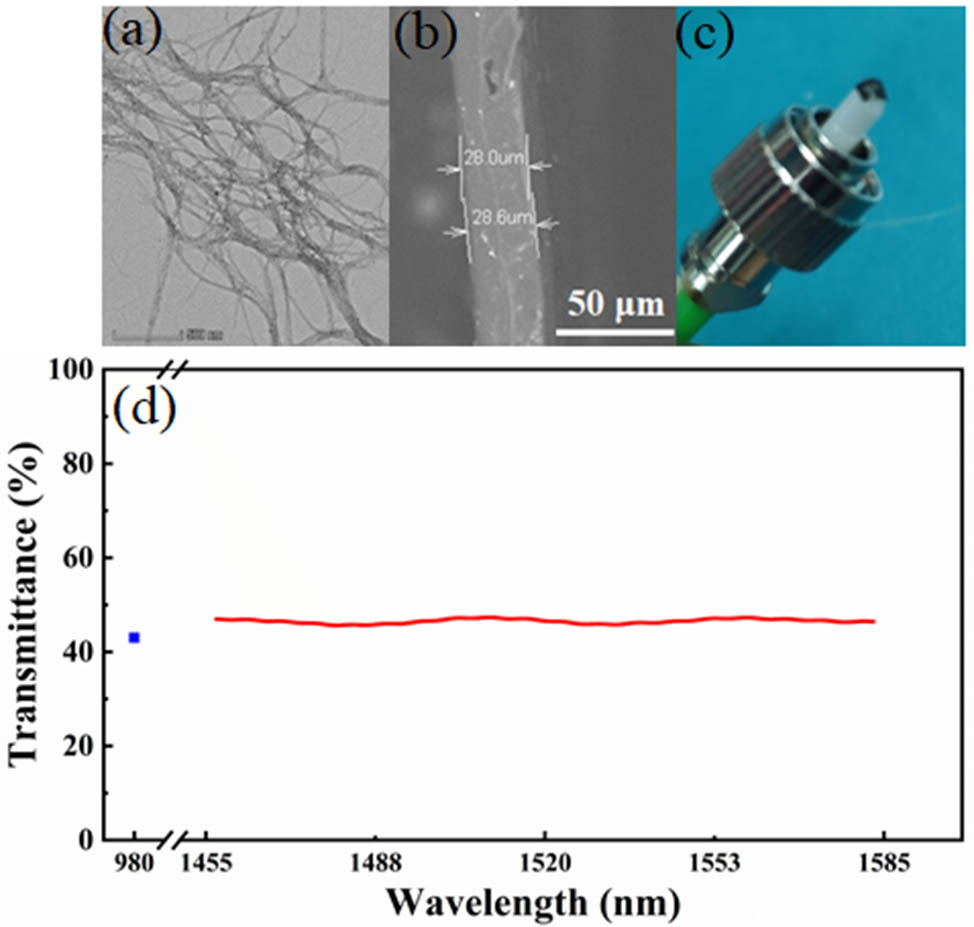
A high-quality CNT-PVA thin film is the key component of the all-optical inverter. The PVA material has a relatively high thermo-optic effect and is easy to mix with CNTs to form a high-quality thin film. There are many other works that used CNT-PVA thin film and show the good performance of this combination[29–31]. The LDM CNTs have a strong third-order optical nonlinearity and an ultra-short recovery time of measured by the pump-probe method[32,33]. By using the catalytic vapor decomposition method, single-wall CNTs with 1 nm to 1.5 nm diameters are synthesized. Then the CNTs are mixed with PVA to form thin films with the following steps. The filiform CNTs are dispersed in the deionized water for 5 h by an ultrasonic cleaner to obtain 0.5 mg/mL CNTs dispersion. The CNTs dispersion is then centrifuged at 12,000g for several hours. The upper supernatant is collected to reduce the unwanted scattering loss. Then the CNTs dispersion is mixed with a 10% (mass fraction) aqueous PVA solution at a 2:1 volume ratio for 3 h by using a magnetic stirrer. Finally, the CNT-PVA mixture is transferred to a clean plastic dish for two-day evaporation to form a thin film. The transmission electron microscope (TEM) image of the CNTs is shown in Fig. 1(a). The thickness of CNT-PVA thin film is measured by a scanning electron microscope (SEM), as shown in Fig. 1(b). Figure 1(c) shows the image of fabricated CNT-PVA thin film transferred on an angled fiber connector. Then the CNT-PVA thin film is sandwiched between two angled fiber connectors (FC/APC) for the experimental usage. The transmission of the CNT-PVA thin film is also measured, as shown in Fig. 1(d). From Fig. 1(d), it can be seen that the transmittance of the CNT-PVA thin film is 43% at 980 nm, corresponding to a 3.7 dB insertion loss, and 47% at 1550 nm, corresponding to a 3.3 dB insertion loss. The film reaches its melting point of when 60 mW power is applied through a fiber, corresponding to a temperature increase of 57°C (assuming room temperature 23°C). So the photo-thermal conversion efficiency of CNT-PVA thin film is estimated to be .
Figure 1.(a) TEM image of the CNTs in the dispersions. (b) The SEM image of the CNT-PVA thin film. (c) The CNT-PVA thin film transferred onto a fiber connector. (d) The transmittance of the CNT-PVA thin film.
Before the experiment of the all-optical inverter, we first investigate the relationship between the insertion loss of the CNT-PVA thin film and the incident optical power of the 980 nm control light (pump). As shown in Fig. 2(a), a fiber MZI is implemented, which mainly consists of a CNT-PVA thin film sandwiched between two angled fiber connectors, a 980 nm control light (pump), a 1550 nm continuous wave (CW) signal light, two wavelength division multiplexers (WDMs), and a delay line. When the 1550 nm signal light is applied, an interference spectrum can be observed on the optical spectrum analyzer due to the unequal arm length in the MZI, as shown in Fig. 2(b). The period in the spectrum is dependent on the delay between the two arms of the MZI. The contrast between the highest transmission and lowest transmission is dependent on the loss difference between the two arms.
Figure 2.(a) Experimental setup to measure the power-dependent loss of the CNT-PVA thin film. (b) The transmission spectra of the MZI at the pump power of 0 mW (black) and 30 mW (red). (c) The change of insertion loss of the CNT-PVA thin film with the increase of pump power (control light) at 980 nm. Inset: the modulated 1550 nm output light at the 30 mW 980 nm control light (pump).
When the 980 nm control light is injected through a WDM, the CNT-PVA thin film absorbs the power and forms a thermal lens due to the thermo-optic effect. A simulation is performed to explain the mechanism of the thermal lens in our device. The simulation result of beam propagation in the CNT-PVA thin film is shown in Fig. 3(a). The thickness of the thin film is 25 μm. The initial beam width is 9.5 μm from a single-mode fiber, corresponding to the position of in Fig. 3(a). The temperature gradient is assumed to be 50°C, that is, the temperature at the position of is 50°C higher than that at . Due to the negative thermo-optic effect of PVA (), an inverse thermal lens is formed along the beam propagation direction, that is, the beam width is expanded during the propagation. As a result, the coupling efficiency is reduced when the beam enters the second fiber at . Figure 3(b) shows the evolution of the beam width during the propagation. It can be clearly observed that the beam diameter is increased from 9.5 μm to .
Figure 3.(a) Simulation of the beam propagation in the heated CNT-PVA thin film. (b) The evolution of beam width.
Due to the reduced coupling efficiency induced by the thermal lens, the insertion loss of the CNT-PVA thin film is increased and the contrast in the transmission spectrum of the MZI is reduced. As shown in Fig. 2(b), it can be clearly observed that the contrast decreases with the increase of the injected 980 nm light power from 0 mW to 40 mW. It is known that the relation between the spectral contrast of an MZI and the loss difference in the two arms[34] is given by and where ER is the extinction ratio of interference spectrum, is the amplitude difference between the two arms, and LD is the power loss difference between the two arms. Therefore, the insertion loss change of the CNT-PVA thin film can be calculated based on the extinction ratio evolution, as shown in Fig. 2(c). It can be observed that as the power of the 980 nm control light (pump) increases, the insertion loss of the LDM CNT-PVA thin film is increased by ∼4 dB. When the power of the 980 nm control light exceeds 60 mW, the CNT-PVA thin film is damaged by the accumulated power. The inset of Fig. 2(c) shows the modulated 1550 nm signal light with a 3 dB extinction ratio when the power of the 980 nm control light (pump) is 30 mW.
The experimental setup of the all-optical inverter is shown in Fig. 4. A 1550 nm CW laser source is used to generate the signal light. The control light (pump) pulse is generated by using the analog modulation port of the 980 nm light source. The signal light and the control light are combined by a WDM. In order to obtain the best output signal, there are two polarization controllers (PCs) to control the polarization states of the signal light and the control light (pump) before the WDM. The CNT-PVA thin film is sandwiched between two FC/APC fiber connectors. The WDM after the CNT thin film is used to filter out the residual 980 nm light. When the 980 nm control light is injected, CNT thin film absorbs the 980 nm control light (pump), generates heat, forms a thermal lens due to the thermo-optic effect, and changes the power of the 1550 nm signal light. Then the output signal of the 1550 nm pulsed light controlled by the 980 nm control light (pump) can be obtained. The output signal is monitored by a 2.5 GHz oscilloscope (Agilent DSO9254A).
Figure 4.Experimental setup of an all-optical inverter with the CNT-PVA thin film.
Figure 5 summarizes the property of the output 1550 nm signal light. We apply the 980 nm control light with a duty cycle of 20%, a frequency of 50 Hz, and a peak power of 40 mW into the all-optical inverter system, as shown in Fig. 5(a) (upper panel). Figure 5(a) (lower panel) shows the output waveform of the 1550 nm signal light. A clear inversion between the output signal and the input control light can be observed. Figure 5(b) shows the enlarged view of the single output 1550 nm pulse. By fitting the front edge (trailing edge) of the output 1550 nm signal light pulse with the exponential function , the time constants of the front and trailing edges are 55 μs and 44 μs, respectively. The fitting curves are shown in Fig. 5(b). The operation speed is estimated to be . In addition, the transition time from 90% to 10% (10% to 90%) optical power is 137 μs (103 μs). The time of the front edge of the output waveform (1550 nm signal light) mainly depends on how fast the control light can heat the CNT-PVA thin film, while the time of the trailing edge is only determined by the heat dissipation in the CNT-PVA thin film when the control light is absent. The long-term stability of the output signal light is also demonstrated, as shown in the Fig. 5(c). Long-time stability of the amplitude of the output pulses can be clearly obtained, which proves that our CNT-PVA-based all-optical inverter device is less sensitive to environmental disturbances. The operational wavelength of the all-optical inverter is dependent on the absorption wavelength of the CNTs. As long as the wavelength can be absorbed by the CNTs, it can be used as a pump wavelength. For the signal wavelength, it should have lower absorption in CNTs and PVA.
Figure 5.(a) Pulsed 980 nm control light (upper) and modulated 1550 nm output signal (lower). (b) A zoomed view of an output signal (black) and exponential fit (red). (c) A long-term stable output.
The time constant of the front (trailing) edge of the output signal light is very important to the all-optical inverter system. We also investigate the relationship between the peak power of 980 nm control light and the time constant of the front (trailing) edge of the output 1550 nm signal light. The control light with a different duty cycle and fixed peak power is applied. The output 1550 nm signal light is shown in Fig. 6(a). The corresponding time constants of the front and trailing edges are summarized in Fig. 6(c). As discussed above, the time constant of the front edge mainly depends on how fast the control light can heat the CNT-PVA thin film. Therefore, the time constants are nearly unchanged for a fixed peak power of control light. Similarly, the time constant of the trailing edge is only determined by the heat dissipation in the CNT-PVA thin film, which is also nearly unchanged.
Figure 6.Output signal pulses and the time constants of the front (trailing) edge when the control light (pump) with different duty cycles and (a), (c) the same peak power or (b), (d) different peak powers are applied.
When the control light with a different peak power and fixed average power (i.e., fixed pulse energy) is applied, the output signal light is shown in Fig. 6(b). The corresponding time constants are summarized in Fig. 6(d). When the control light has a higher peak power, due to the limited bandwidth of the device (caused by the slow response of the thermal effect), the rising time is increased and the heating process is lengthened. As a result, the time constant for the front edge also increases. Similarly, the time constant of the trailing edge is also increased. When the duty cycle reaches 10%, the corresponding peak power of the control light is , which exceeds the damage threshold of the thin film. Therefore, the experiment with 10% duty cycle is not performed.
Compared with the all-optical signal processing based on the saturable absorption of low-dimensional materials (LDMs)[35–38], the saturable absorption can provide a very fast response (ps to fs level) and support high-speed operation. However, its modulation depth is typically less than 10%. Therefore, to obtain a better modulation depth, we adopt the thermo-optic effect as our working mechanism. As can be seen, the modulation depth can be 50%.
To verify the thermal accumulation property of the CNT-PVA thin film, a burst of pulses with a period of 2 ms is applied. Each burst includes three pules at 980 nm with a frequency of 4 kHz and a duty cycle of 90%. The waveforms of the 980 nm control light (upper panel) and the output 1550 nm signal light (lower panel) are shown in Fig. 7. It can be observed that the output 1550 nm signal light shows the increased negative amplitude in a burst period, which is very similar to the charge-discharge behavior of a capacitance. It is a clear demonstration of the thermal accumulation property of the device.
Figure 7.(a) Burst of the control light (pump). (b) The signal output.
To further investigate the response bandwidth of the all-optical inverter, the 980 nm control light (pump) modulated by a sine wave from 50 Hz to 12 kHz is applied. As shown in Fig. 8(a), when the amplitude of the sine wave is fixed and the frequency of the sine wave gradually increases, the peak-to-peak voltages of the output signal waveforms gradually decrease due to the slow thermo-optic effect. In addition, it is obvious in Fig. 8(b) that when the frequency is fixed and the amplitude of the sine wave of the 980 nm control light (pump) is raised, the peak-to-peak voltage of the output signal also increases. However, the difference is gradually weakened with the increase of the amplitude. This is due to the fact that the CNT-PVA thin film gradually reaches the saturation state. The 3 dB bandwidth of the all-optical inverter where the amplitude drops to half of the maximum amplitude is .
Figure 8.(a) Output signals with different amplitudes of the 980 nm control light at different frequencies of the 980 nm sine wave control light; (b) the corresponding peak-to-peak amplitudes.
In conclusion, we demonstrate an all-optical inverter based on the thermal lens effect in CNT-PVA thin film. It has a front (trailing) time constant of (44 μs) for 1550 nm signal pulses. The response bandwidth is . Long-term stability of the output signal is also demonstrated due to the environmental insensitivity of the device. The compactness and high stability of the device indicate the potential of LDM in all-optical communications and signal processing systems.