
Hao WANG, Yue-gang FU, Guo-yu ZHANG, Gao-fei SUN, Shi LIU, Jian ZHANG, Da XU, Ling-hao WU, Jun-jie YANG. Concentration Performance Analysis of Solar Simulator Based on Compound Parabolic Concentrator[J]. Acta Photonica Sinica, 2020, 49(12): 1
- Acta Photonica Sinica
- Vol. 49, Issue 12, 1 (2020)
Abstract
Keywords
0 Introduction
A solar simulator is a radiation of equipment capable of producing light sources with characteristics similar to the geometrical and irradiation features of the sun. The optical system of simulator comprises a light source, a condensing system, a uniform light system, and a collimating system. The light source typically employs a xenon lamp with an output that matches the solar spectrum. The condensing system uses an ellipsoidal condensing mirror. An optical integrator is used in the uniform light system. These systems are matched with one another to realize the solar radiation simulation. This approach is widely used and is important in the aerospace, meteorological, and photovoltaic industries, among others.
A Compound Parabolic Concentrator(CPC) is generally used as a heat collector in the field of solar energy[
Research on the design method of the compound parabolic concentrator used in a solar simulator, the CPC was designed based on the edge ray principle. The optical system’s simulation model was established using LightTools. The light collection efficiency of the simulated beam in the CPC and the ellipsoidal condenser was compared and analyzed. The problem of low energy utilization in solar simulators presents new ideas for the research on concentrating systems.
1 Composition and working principle of solar simulator optical system
The solar simulator employs a coaxial transmission collimation system. The optical system mainly comprises a xenon lamp, a concentrating system (a spherical reflector and the CPC), a shaping system, an optical integrator, a diaphragm, and a collimation lens group, as shown in Fig. 1.

A short-arc xenon lamp is used as the light source for the solar simulator. The luminous xenon arc between the cathode and anode of the xenon lamp is placed at the focal plane of the CPC. The light emitted by the xenon lamp exits the spherical reflector and the CPC. Then, the outgoing light beam is projected onto the optical integrator through the lens. In the integrator, the light beam is divided by the field mirror and then superimposed and imaged by the projection mirror.The light beam is projected onto the irradiation surface through the diaphragm and the collimation lens group to form a uniform and collimated light spot, thus achieving the simulating solar irradiation.
2 Design of concentrating system
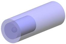
Based on the path reversal principle, the CPC is designed as a reflective glass. The light source is placed in the exit hole; the light then exits the entrance hole at a particular angle and the addition of a spherical reflector prevented the loss of direct backward light from and made effective use of it. The CPC can achieve the maximum theoretical concentration ratio[
The light collection efficiency of the ellipsoidal condenser and the CPC can be calculated using the ratio of the radiant flux received by the irradiated surface to the radiant flux emitted by the light source, as shown below in Eq. (1).
where is the concentrating efficiency, t(u) = I/I0 indicates the relative distribution of the irradiance of the light source in different directions, I0 is the normal luminous intensity of the light source, I is any light intensity in the direction of angle u with the light source axis, and u0 and um are the containment angles. The above equation indicated that the light collection efficiency differed under different containment angles. The maximum containment angle of the ellipsoidal condenser was 30°~135°[
2.1 Concentrating principle of CPC
The CPC's concentrating principle is edge ray principle. For a light beam entering a large aperture of the CPC at the maximum incidence angle, the edge light must exit from the edge of the small aperture; that is, the light emitted from the edge of the light source should reach the edge of the target. As shown in Fig.2, the AB segment in the parabola is intercepted and rotated around the central axis OY' to form a three-dimensional CPC. Point A' is the focus of parabola AB and point A is the focus of parabola A'B'. The focal points of the two curves are not at the same point. As such,this is a nonconfocal system in the context of nonimaging optics[
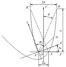
Analysis of Fig.2 provided an understanding of the relationship between the parameters and facilitation of the overall design. The equation for parabolic AB is expressed as Eq. (2).
when , then , then Eq. (3) below can be derived from Eq. (2).
Eq.(3) enables deriving the relationship between the entrance aperture and the length of the CPC[
2.2 Parameter design of the CPC
With an understanding of the working principle of the CPC, to conveniently establish a CPC model, the calculation formula of each parameter was deduced. The CPC in the X'OY' rectangular coordinate system was extracted into the polar coordinate system XA'Y, and the parabolic polar coordinate equation was used to analyze the CPC's parameter design[
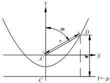
In Fig.3, D is an arbitrary point on the parabola, A' is the focus of the parabola, and the straight line is the guideline of the parabola. The focal length of the parabola is and the equation of the parabola is y=.
Using the definition of the parabola, the distance from any point on the parabola to the fixed point was equal to the distance from the point to the fixed line, and Eq. (4) below could be obtained.
In Eq.(4), is the distance of A'D andis the angle between A'D and the Y-axis.when, then , substituting Eq. (4) can deduce that the maximum receiving angle satisfies Eq. (5).
The length L of the CPC obtained by the sine theorem is shown in Eq. (6).
when and are determined, the parameters , , and can be obtained from Eq. (6), and can be obtained from Eq. (7) below. Following the simulation analysis, the ideal angle was obtained. Following this design process, the geometric structure of the CPC was determined.
The exit aperture of the CPC had to support the installation of the xenon lamp light source and ensure a degree of radial adjustment margin, as shown in Eq. (7) [
In Eq. (7), d is the shell diameter of the selected xenon lamp (60 mm) and Δ is the radial adjustment margin (2 mm). Then, mm is obtained (32 mm), and the exit aperture is determined as being 64 mm.
2.3 Design of the spherical mirror
The spherical mirror was designed based on the CPC parameters. Its radius had the same parameters as that of exit aperture of the CPC. The center of the sphere was located at the light source. The lower aperture and the upper aperture had to satisfy Eq. (8). The xenon lamp could be placed between the combined mirrors to realize the effective use of the light beam.
In Eq. (8), is the aperture of the lower opening of the spherical reflector, is the diameter of the xenon lamp holder, and is the aperture of the upper opening of the spherical reflector.
3 Simulation analysis
Analysis and study of the utilization of the CPC in the solar simulator, alongside a sensible design of the CPC's external dimensions, effectively improved the energy utilization of the light source. Using the LightTools software, a physical model of the CPC was created and the ideal acceptance angle was analyzed and determined. The CPC profile parameters calculated in the above equations were used as input, suitable materials and surface properties were determined, and the optimal interception ratio was selected to simplify the CPC's overall structure.
3.1 Light source modeling
A short-arc xenon lamp is typically used as the light source for a solar simulator. Its advantage is that the spectral distribution of the xenon lamp is close to that of actual sunlight, exhibits strong stability[
Based on the lamp brightness curve in LightTools, the light-emitting area of the xenon lamp was divided into three parts, three sub-light source models were used to simulate the light emission of the three subareas, and a certain proportion of power was allocated. The volume light source model is shown in Fig.4.
3.2 CPC's simulation modeling
The main method of measuring the performance of the condenser was to analyze its optical efficiency, that is, to transmit a high percentage of the light emitted from the front surface to the exit hole[
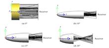
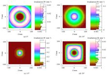
The radiation flux of the receiving surface under each receiving angle was 960.9 W, 1 107 W, 1 070 W, and 399.2 W. Considering factors such as structure and irradiance, the CPC was designed with a maximum acceptance angle of 15°.
Compared with the traditional condenser, the aspect ratio of the CPC was extremely large[
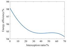
Fig.7 shows that the efficiency of the concentrating system was still able to reach 94% after intercepting 70% of the CPC, indicating that the intercept ratio had little effect on the concentrating efficiency. The intercept ratio was set at 60% and the concentrating efficiency remained high, which solved the shortcomings of the CPC aspect ratio being extremely large.
3.3 Analysis of simulation results
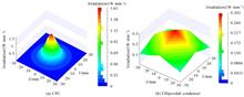
After determining the CPC at the optimal intercept ratio, the light was traced in LightTools, and an irradiance image was obtained at the grid diameter of 50 mm on the receiving surface. As shown in Fig.8(a), from the grid data, the radiant flux received on the receiving plane was 1 921 W, and the calculated light collection efficiency reached 94.86%. The ellipsoidal condenser was then simulated under the same light source, the same working distance, and the same irradiation surface. As shown in Fig.8(b), the radiant flux on the receiving surface was 1 317 W, and the light collection efficiency was only 65%. These results indicated that the CPC-based light collection system had much higher light collection efficiency compared with the traditional light collector (ellipsoidal condenser)[
It can be seen from Table 1 that the CPC concentrating system had a great improvement in energy utilization compared with the traditional concentrating system.
| Structure | Radiant flux/W | Irradiation surface incident energy/W | Light source utilization/% |
|---|---|---|---|
| Single ellipsoidal mirror | 2 025 | 1 317.2 | 65 |
| CPC concentrating system | 2 025 | 1 921 | 94.86 |
Table 1. Performance simulation comparison between CPC combined concentrating system and ellipsoidal concentrating system
The overall simulation diagram of the solar simulator is shown in Fig.9. The raster chart of the irradiated surface is shown in Fig.10.

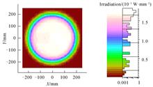
Fig.10 shows that when the CPC was applied to the solar simulator, the improvement in the light collection efficiency also effectively improved the irradiance of the solar simulator.
4 Experimental verification
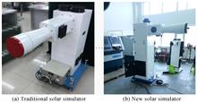
Regarding the solar simulator in the above design, the irradiance and irradiance uniformity tests were performed at a working distance of 2 m using an irradince meter. The experimental devices of the traditional and new solar simulators are shown in Fig.11.
Under the same power source two solar simulators were tested, a test grid was divided on the surface perpendicular to the optical axis. The grid diameter was 400 mm and a test point was set every 45° at the edge of the grid, for a total of eight edge test points and one center test point. The test data obtained subsequent to the measurements are listed in Table 2 below.
| Test point | Center point | 1 | 2 | 3 | 4 | 5 | 6 | 7 | 8 |
|---|---|---|---|---|---|---|---|---|---|
| Traditional solar simulator irradiance/(W·m-2) | 1 079 | 1 043 | 1 053 | 1 062 | 1 034 | 1 009 | 995 | 1 036 | 1 055 |
| New solar simulator irradiance/(W·m-2) | 1 578 | 1 542 | 1 525 | 1 503 | 1 488 | 1 473 | 1 490 | 1 511 | 1 532 |
Table 2. Comparison of irradiance test data
As shown in the table above, the highest irradiance at the center point was 1 578 W/m2, whereas the lowest (at the fifth test point) was 1 473 W/m2. The nonuniformity of irradiation was calculated as 3.4%. Experimental results were consistent with the simulation results.Compared with the traditional solar simulator, the new solar simulator had higher irradiance, which showed that the energy utilization was effectively improved.
5 Conclusion
This study proposed using a CPC to improve a solar simulator's concentrating system and to optimize the latter's overall design to achieve improvements in the solar simulator energy utilization and irradiance. First, the difference in the concentrating efficiency between the CPC and ellipsoidal condenser was analyzed, and the structural parameters were derived based on the working principle of the CPC. A nested model comprising a xenon lamp body light source and a CPC was established, and the irradiation distribution under different maximum receiving angles was analyzed to determine an ideal receiving angle of 15°. The light-collecting ability of the ellipsoidal mirror and the CPC was compared and analyzed. Simulation results showed that the energy utilization rate of the CPC and the spherical mirror was able to reach 94.86%, higher than that of the ellipsoidal condenser. When simplifying the CPC structure through interception, it was found that 60% interception had little effect on energy utilization and was beneficial to actual processing and manufacturing. Finally, the Monte Carlo method was applied to simulate the overall optical system of the solar simulator. Results delivered good irradiation results, the irradiance was verified to be higher by the test, and nonuniformity of irradiation reached 3.4%. Analysis results presented herein are conducive to the improvement of the overall efficiency of the solar simulator and provide new ideas for the design of high-irradiance solar simulators.
References
[1] E BELLOS, D KORRES, C TZIVANIDIS. Design, simulation and optimization of a compound parabolic collector. Sustainable Energy Technologies and Assessments, 16, 53-63(2016).
[2] Ya-xian WANG, Wen-qing XU. Research on the key technology of shipboard LED search light. Optics & Optoelectronic Technology, 13, 70-74(2015).
[3] V ANDREEV, A KAZANTSEV, V KHVOSTIKOV. 6% AM 0) LPE grown AlGaAs/GaAs concentrator solar cells and modules, 2, 2096-2099(1994).
[4] Pian HU, Yan LIU, Shu-guang ZENG. Effects of compound parabolic concentrator parameters on the concentration efficiency of solar lasers. Laser Journal, 38, 8-11(2017).
[5] Li-feng LI, Bao WANG, J POTTAS. Design of a compound parabolic concentrator for a multi-source high-flux solar simulator. Solar Energy, 183, 805-811(2019).
[6] Ling-zhi LIU, Jian-hong LI. Research on optical analysis of compound parabolic concentrator (CPC). Energy Technology, 52-56+59(2006).
[7] Tao LV, Jing-xu ZHANG, Dong-hui FU. Determination of parameters of ellipsoidal condenser in solar simulator. Journal of Applied Optics, 35, 43-47(2014).
[8] Le WANG, Shu-sheng ZHANG, Jing ZHAI. Research on modeling of LED reflector based on compound parabolic concentrator. Laser & Optoelectronics Progress, 49, 159-164(2012).
[9] Fei WANG, SUI Cheng-hua, Bi-qing YE. Research on the design parameters of compound parabolic concentrators. Optical Instruments, 32, 68-72(2010).
[10] Lei JIANG. Design and research of Fresnel lens and compound parabolic concentrator(2011).
[11] Pei-yu SONG. Design and simulation analysis of high collimation and high irradiance solar simulator(2017).
[12] V ESEN, B ORAL. Light sources of solar simulators for photovoltaic devices: A review. Renewable and Sustainable Energy Reviews, 77, 1240-1250(2017).
[13] S ABU-BAKAR, F MUHAMMAD-SUKKI, D FREIER. Performance analysis of a novel rotationally asymmetrical compound parabolic concentrator. Applied Energy, 154, 221-231(2015).
[14] Ming MA, Hong-fei ZHENG, Jia-chun LI. The influence of the compound parabolic concentrator (CPC) truncation on its performance. Solar Energy, 33-36(2011).
[15] Gao-fei SUN, Wen-peng WANG, Guo-yu ZHANG. Design and simulation of high irradiance multi-collimate angle solar simulation optical system. Acta Energiae Solaris Sinica, 39, 2209-2216(2018).


Set citation alerts for the article
Please enter your email address
© Copyright 2018-2021 | Chinese Laser Press. All Rights Reserved 沪ICP备15018463号-20