Abstract
This Letter presents a double-layer structure combining a cracked cross meta-surface and grating surface to realize arbitrary incident linear terahertz (THz) wave polarization conversion. The arbitrary incident linear polarization THz wave will be induced with the same resonant modes in the unit cell, which results in polarization conversion insensitive to the linear polarization angle. Moreover, the zigzag-shaped resonant surface current leads to a strong magnetic resonance between the meta-surface and gratings, which enhances the conversion efficiency. The experimental results show that a more than 70% conversion rate can be achieved under arbitrary linear polarization within a wide frequency band. Moreover, around 0.89 THz nearly perfect polarization conversion is realized.Terahertz (THz) science and technology have rapidly been becoming the focus in the fields of information and communication technology, sensing, and imaging[1–7]. Towards these applications, high-performance THz components become essential for manipulating THz waves[3–12]. Since polarization is one of the most significant properties of manipulating electromagnetic (EM) waves in many aspects such as the THz spectroscopy, THz imaging system, and THz radar system, manipulation of the polarization of the THz wave has attracted more and more concerns[13–17]. There are some conventional methods to manipulate the polarization, including the use of photo-elastic modulators, birefringence effects, and optical grating[18–20]. These methods generally require a long propagation distance to acquire the phase accumulation and involve the use of large equipment. However, it is essential for polarization converters to control the polarization state in compact communication and spectroscopy. Thus, exploring the application of both lightweight and compact polarization control equipment is desirable.
Recently, a series of new-type polarization converters have been realized by applying different metamaterial microstructure designs, and these devices were demonstrated for conversion between different polarization states, such as linear to linear[21–24], linear to circular[25–28], and linear to cross polarization[29,30].
However, most of these converters are dependent on the polarization of the incident THz wave, which limited their practical applications.
Sign up for Chinese Optics Letters TOC. Get the latest issue of Chinese Optics Letters delivered right to you!Sign up now
Here, based on the concept of metamaterials, the convertor comprises an array of cracked cross resonators, and a grating surface at the bottom has been proposed to convert the arbitrary linear waves into the -polarized wave. Both theoretical and simulation results show that this structure can realize a relatively high conversion rate with only a two-layer structure.
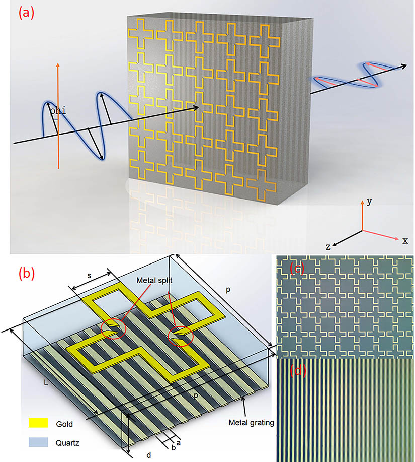
The convertor is composed of three parts: the upper cracked cross meta-surface layer, the quartz substrate, and the lower grating surface. A schematic configuration of the proposed polarization convertor is described in Fig. 1(a). A unit cell of the structure is composed of a 45° slanted open metal cross and a traditional wire-grid surface placed near the ground plane and separated by a 253 μm thick quartz dielectric spacer, as shown in Fig. 1(b). The designed size parameters are , , and . The bottom metallic grating layer is designed to be parallel to the y axis, and the structure parameters are and . As shown in Figs. 1(c) and 1(d), the gray part is quartz, and the bright yellow part is gold. The incident linearly-polarized THz wave is projected perpendicularly to the structure with arbitrary polarization angle phi, which is the angle between the polarization direction of the incident THz wave and the axis. The upper meta-surface layer plays a significant role in resonating with the arbitrarily polarized waves in the same EM mode so that they can have nearly same EM characteristics in the substrate. The lower gratings act as the polarization selective surface. Moreover, a micro Fabry–Pérot (FP) cavity is constructed from the upper meta-surface and lower grating surface, which can enhance the conversion efficiency.

Figure 1.(a) Schematic of the sample used in the experiment. (b) A unit cell structure. (c) The photo of the manufactured top structure. (d) The photo of the manufactured bottom structure.
To get insight into the underlying mechanism of the polarization converter, simulations based on the finite element method (FEM) are performed by applying the frequency-domain solver of the CST Microwave Studio software. In the simulation, a single unit cell with periodic boundary conditions along the and directions is employed, and the arbitrary linear THz wave is utilized to illuminate the meta-surface.
The polarization conversion ratio (PCR) is defined as the rate of output -polarized THz wave intensity to arbitrary input angle polarized wave intensity. Figure 2 shows the simulated PCR as a function of frequency. It is shown that the PCR of the structure is roughly above 70% at all angles of incidence, ranging from 0.92 to 0.99 THz. Besides, the conversion efficiency reaches up to 100% around 0.893 THz at 0°, as shown in Fig. 2(a). These results show that such a device is insensitive to the linear polarization of the incident wave, and the conversion ratio is relatively high.
Figure 2.Spectra of the PCR ranging from 0° to 90°.
On the other hand, in a physical explanation, as the polarization direction of the incident electric field rotates, the actual length of the electric cross section of the metal cross structure will change slightly, resulting in frequency shifting.
The incident wave with arbitrary angular polarization can be decomposed into a combination of - and -polarized waves. Therefore, we analyze the THz waves with - and -polarized incident waves. In order to study the mechanism, the analysis of the resonant mode has been carried out. At the first stage, the arbitrary incident linear THz wave can be decomposed in the orthogonal plane as -polarized and -polarized components. We choose two different representative resonant frequencies of 0.893 THz (maximum conversion point) and 0.95 THz (high conversion band) to observe the contour maps of the resonant modes induced by -polarized and -polarized electric components independently.
Figures 3(a) and 3(b) show the contour map of the resonant modes induced by -polarized and -polarized electric components at 0.893 THz. For THz waves incident in different directions, strong responses are produced at the metal split, but the modes are different. Moreover, from the surface current distribution results shown in Figs. 3(c) and 3(d), it also illustrates that both the -polarized and -polarized components could induce different current flows at 0.893 THz. Therefore, the response of the x and y directions is different. For the high conversion band, such as 0.95 THz, shown in Fig. 3(e)–3(h), for the THz wave incident in the directions of x and y, the same mode is excited, so it is not sensitive to the incident angle. Therefore, the proposed type of half-wave meta-surface is designed in the mechanism by controlling the spectral response of the - and -polarization components having equal amplitudes at the designed frequency.
Figure 3.Electric field distribution on cracked cross meta-surface for incident -polarized waves at (a) 0.893 THz, (e) 0.95 THz. Electric field distribution on cracked cross meta-surface for incident -polarized waves at (b) 0.893 THz, (f) 0.95 THz. Surface current distribution on cracked cross meta-surface for incident -polarized waves at (c) 0.893 THz, (g) 0.95 THz. Surface current distribution on cracked cross meta-surface for incident -polarized waves at (d) 0.893 THz, (h) 0.95 THz.
This phenomenon indicates that the arbitrary incident linear THz wave will induce similar EM resonant modes at the upper meta-surface so that nearly the same EM field components will transmit through the spacer and reach the lower surface. Therefore, such a meta-surface can convert arbitrary linear waves into -polarized waves.
Secondly, it can be found from the surface current distribution that the zigzag surface current has two flows: the transverse ( direction) and longitudinal ( direction) directions. As shown in Fig. 4(a), the vertical magnetic field led to an electromotive force along the grating, which results in an induction current flow in the longitudinal direction. Both the upper induced surface current and the lower induction current along the grating have the same flow direction, so the inductive coupling will take place and enhance the conversion efficiency.
Figure 4.(a) Schematic diagram of magnetic field coupling conversion. (b) Scheme of the multiple reflection–transmission processes of polarization. (c) Magnetic field in the direction of . (d) Magnetic field in the direction of .
Due to the polarization selective characteristics of the grating surface, when the -polarized EM wave is incident on the surface of the metal grating with a large duty ratio, it would reflect the -polarized incoming wave. On the contrary, when the incident wave polarized is in the direction, the movement of electrons is due to the gap between the gratings, which makes the incident wave completely transmitted. Besides, the reflected wave decomposes again after passing through the surface metal through the quartz spacer. Some of them return to the button metal surface and transmit the vertical component. As shown in Fig. 4(b), after multiple reflections and transformations, more vertical components are transmitted. The dielectric layer and the metal structure of the upper and lower surfaces form a structure similar to the FP cavity. The magnetic field in the and directions is shown in Fig. 4(c) and 4(d), indicating the FP resonant mode in quartz. The actual conversion bandwidth is determined by the cracked cross meta-surface at the top layer, as shown in Fig. 4(e); with the decrease of L, the conversion band becomes narrow. Both the magnetic field conversion coupling and the FP resonant cavity can improve the conversion efficiency to polarization.
To validate the aforementioned multifunction, a sample containing 100 × 100 unit cells with a side length of 1.1 cm is fabricated and measured. After photolithography, electron-beam metal deposition, high-accuracy alignment, and lift-off fabrication process, the top and bottom meta-surfaces with 200 nm gold metal can be achieved. The high-resolution THz time-domain spectrometer (TDS), which is produced by Teraview Company, is utilized in the system setup. The schematic of the experimental system is shown in Fig. 5(a). The polarization converter sample is located onto the freely rotating dial plate at the focus of parabolic mirrors, as shown in Fig. 5(b). The polarized THz wave is focused by parabolic mirrors, which are parallel to the optical platform. We gradually rotate the dial and record the intensity and rotation angle of the polarized THz wave signal by the receiver at the same time. By applying the fast Fourier transformation (FFT), the transmittance of different linear polarization angles could be retrieved as Fig. 5(c).
Figure 5.(a) Schematic diagram of the THz-TDS test system. (b) Photo of THz-TDS test system. (c) Transmission when the THz wave is incident on the THz polarization converter in different polarization directions by experiment. (d) Comparison between the experiment and simulation.
The experimental results depict that this device can convert arbitrary linear polarization into the -polarization wave; around 0.91 THz, the highest conversion ratio can reach 99%.
Obviously, there is a big difference between simulation and experimental results. After the experiment, we measured the thickness of the tested sample. The thickness of the thinned sample is 240–255 μm. After simulation comparison, we reduce the quartz thickness to 240 μm and adjust the metal linewidth to 4 μm. The simulation results are in good agreement with the experimental results, as shown in Fig. 5(d). Therefore, the error of the test results is mainly due to the machining error.
In conclusion, we have numerically and experimentally demonstrated a double-layer structure converter with a cracked cross meta-surface and grating surface, which achieves 97% PCR with the arbitrary incident linearly-polarized THz wave around 0.9 THz. It is found that the -polarized and -polarized electric components can induce the same resonant mode in the meta-unit, and, due to inductive coupling, the conversion efficiency is relatively high. The experimental results agree with the simulation very well. It shows promising applications in the manipulation of polarization of THz regions.
References
[1] V. Savinov, V. A. Fedotov, S. M. Anlage, P. A. J. De Groot, N. I. Zheludev. Phys. Rev. Lett., 109, 243904(2012).
[2] N. I. Zheludev, Y. S. Kivshar. Nat. Mater., 11, 917(2012).
[3] H. Zhang, P. Guo, P. Chen, S. Chang, J. Yuan. J. Opt. Soc. Am. B, 26, 101(2009).
[4] Y. Zhao, A. Alù. Phys. Rev. B, 84, 205428(2011).
[5] B. Scherger, C. Jördens, M. Koch. Opt. Express, 19, 4528(2011).
[6] Q. Xu, X. Q. Zhang, Y. H. Xu, C. M. Ouyang, Y. F. Li, J. G. Han, W. Zhang. Chin. Opt. Lett., 16, 050002(2018).
[7] G. Litmanovitch, D. Rrotshild, A. Abramovich. Chin. Opt. Lett., 15, 011101(2017).
[8] J. B. Liu, P. J. Li, Y. F. Chen, X. B. Song, F. Qi, B. J. Zheng, J. R. He, Q. Y. Wen, W. L. Zhang. Chin. Opt. Lett., 14, 052301(2016).
[9] H.-T. Chen, W. J. Padilla, M. J. Cich, A. K. Azad, R. D. Averitt, A. J. Taylor. Nat. Photon., 3, 148(2009).
[10] R. Ulbricht, E. Hendry, J. Shan, T. F. Heinz, M. Bonn. Rev. Mod. Phys., 83, 543(2011).
[11] L. Chen, Y. M. Wei, X. F. Zang, Y. M. Zhu, S. L. Zhuang. Sci. Rep., 6, 22027(2016).
[12] L. Chen, N. N. Xu, L. Singh, T. J. Cui, R. J. Singh, Y. M. Zhu, W. L. Zhang. Adv. Opt. Mater., 5, 1600960(2017).
[13] Y. Z. Cheng, W. Withayachumnankul, A. Upadhyay, D. Headland, Y. Nie, R. Z. Gong, M. Bhaskaran, S. Sriram, D. Abbott. Appl. Phys. Lett., 105, 181111(2014).
[14] X. Wen, J. Zheng. Opt. Express, 22, 28292(2014).
[15] J. Ding, B. Arigong, H. Ren, M. Zhou, J. Shao, Y. Lin, H. Zhang. Opt. Express, 22, 29143(2014).
[16] N. K. Grady, J. E. Heyes, D. R. Chowdhury, Y. Zeng, M. T. Reiten, A. K. Azad, A. J. Taylor, D. A. R. Dalvit, H.-T. Chen. Science, 340, 1304(2013).
[17] L. Cong, W. Cao, X. Zhang, Z. Tian, J. Gu, R. Singh, J. Han, W. Zhang. Appl. Phys. Lett., 103, 171107(2013).
[18] K. Lee, J. Ko, J. H. Jo, J. Chung. Fusion Eng. Des., 121, 301(2017).
[19] J. C. Zi, Q. Xu, Q. Wang, C. X. Tian, Y. F. Lia, X. X. Zhang, J. G. Han, W. L. Zhang. Opt. Commun., 416, 130(2018).
[20] L. P. Hou, S. Tang, B. Hou, S. Liang, J. H. Marsh. IEEE J. Sel. Top. Quantum Electron., 24, 1102508(2018).
[21] L. Cong, W. Cao, X. Zhang, Z. Tian, J. Gu, R. Singh, W. Zhang. Appl. Phys. Lett., 103, 171107(2013).
[22] J. M. Woo, S. Hussain, J. Jang. Sci. Rep., 7, 42952(2017).
[23] P. Bouchon, F. Pardo. Appl. Phys. Lett., 104, 513(2014).
[24] J. C. Zi, Q. Xu, Q. Wang, C. X. Tian, Y. F. Li, X. X. Zhang, J. G. Han, W. L. Zhang. Appl. Phys. Lett., 113, 101104(2018).
[25] J. Hao, Y. Yuan, L. Ran, T. Jiang, J. A. Kong, C. T. Chan, L. Zhou. Phys. Rev. Lett., 99, 063908(2007).
[26] W. Sun, Q. He, J. Hao, L. Zhou. Opt. Lett., 36, 927(2011).
[27] X. Gao, W. L. Yang, H. F. Ma, Q. Cheng, X. H. Yu, T. J. Cui. IEEE Trans. Antenna Propag., 66, 6086(2018).
[28] H. C. Yu, X. Y. Cao, J. Gao, H. H. Yang, L. Jidi, J. F. Han, T. Li. Opt. Mater. Express, 8, 3373(2018).
[29] X. Gao, X. Han, W.-P. Cao, H. O. Li, H. F. Ma, T. J. Cui. IEEE Trans. Antennas Propag., 63, 3522(2015).
[30] J. Xu, R. Q. Li, S. Y. Wang, T. C. Han. Opt. Express, 26, 26235(2018).