
Alexey V. Gorevoy, Alexander S. Machikhin, Grigoriy N. Martynov, Vitold E. Pozhar. Spatiospectral transformation of noncollimated light beams diffracted by ultrasound in birefringent crystals[J]. Photonics Research, 2021, 9(5): 687
- Photonics Research
- Vol. 9, Issue 5, 687 (2021)
Abstract
1. Introduction
Acousto-optic (AO) interaction is mainly associated with light diffraction by ultrasound waves in solid, liquid, and gas media [1–3]. Depending on the properties of the medium and the relationship between light and sound parameters, this phenomenon may be used for spectral and spatial filtration, deflection, intensity modulation, and other transformations of the incident beam [4,5]. Devices based on this principle have multiple applications in optical engineering and photonics. The main equations describing AO interaction (phase-matching conditions) may be derived from the laws of conservation of energy and momentum for photons and a phonon:
The second equality in Eq. (2) is the convolution integral, where the acoustic field distribution may be considered as the impulse response for monochromatic plane light wave of amplitude : . According to Eq. (3), length and direction of vector have a strong dependence on the refractive indices and and may be represented as a function of , , and . Thus, the main features of diffracted light field distribution are defined both by the structure of the acoustic field and the refractive properties of the medium. Therefore, light beam profile transformation as well as the key parameters of the AO device is defined by the spatiospectral phase matching Eq. (2). This is especially crucial for spectral imaging and other AO applications related to wide angular aperture and wide spectral bandwidth of the incident light [7–9].
In this study, we show that spectral and angular characteristics of AO interaction are inseparable. This means the inevitable presence of residual spatially nonuniform chromatic aberrations in the diffracted beam after AO spectral filtration. For this purpose, we have theoretically and experimentally studied the transmission function for AO Bragg diffraction in birefringent crystal —the most effective and widely used AO material [10]. First, we derive the key formulas representing the angular and spectral dependencies of the phase mismatch. Second, we analyze the geometry of the phase-matching locus and demonstrate its topological diversity. Third, we support the theoretical analysis with experimental investigation.
Sign up for Photonics Research TOC. Get the latest issue of Photonics Research delivered right to you!Sign up now
2. Theoretical considerations
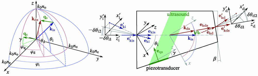
Figure 1.General wavevector diagram (left part) and schematic configuration of the AO cell (right part) for anisotropic (
For description of optical beam transformation, we introduce coordinate systems for input and diffracted beams in the following way. For convenience, we consider the normal incidence on the input facet, so . The axes and are directed parallel to the optical beam trajectory. To find the angular transmission function, one needs to trace the pathway of each partial angular component of the input beam.
As the AO cell geometry is specified by the directions of incident light and sound , then the acoustic frequency satisfying Eq. (1b) and Eq. (3) for a wavelength may be calculated (for interaction) as [12]
To describe AO diffraction of a divergent or convergent light beam, we decompose an input angular 2D distribution into a plane-wave spectrum and calculate diffracted light field distribution according to Eqs. (2) and (3). The commonly used analytical method describes the light beam transformation caused by diffraction on plane sound wave by introducing a wavevector mismatch into Eq. (1b) [11]:
![]()
Figure 2.Surface
The spectral dependence of the transmission function for each direction follows the shape of the sinc-squared function as defined by Eq. (9), but the location of its maximum is defined by the shape of the surface . This spatiospectral dependency is rather complicated and should be taken into account in imaging applications. The spectral and angular cross sections of the function can be analyzed to calculate the spectral and angular bandwidth of the AO device [12,15,16], i.e., its spectral resolution and angular aperture, as well as to describe the angular structure of the output light beam at particular wavelength [9].
![]()
Figure 3.Map of the normalized transmission functions
3. Experimental study
![]()
Figure 4.Experimental setup for measuring 2D transmission functions: MC, monochromator; D, diffuser plate; L1, L2, L3, lenses; P1, P2, polarizers; AOTF, acousto-optical tunable filter; C, camera.
The experimental images were transformed to angular coordinates with regard to focal length of lens L3 and pixel pitch of the camera C, so that the intensity in the resulting image characterizes the AOTF transmission at the corresponding angles. To validate the described theoretical considerations against the experiment, we have modeled the diffracted light images under the same parameters. The simulated images were obtained by summing the calculated transmission function values as follows:
![]()
Figure 5.(a) Simulated (upper row) and experimental (lower row) images
While the components with a wavelength equal to the center of the AOTF transmission window pass through the center of the aperture, the mismatched components tend to pass differently. As can be seen from Fig. 5(b), the central wavelength of the transmission window for is shifted by about 3.5 nm. In practice, this means not only the spatiospectral inhomogeneity but also a broader spectrum of a transmission function across the whole angular aperture. In our experiments, we have found out that even for a constant acoustic frequency applied to AOTF, the diffracted light spectrum may span almost within 9 nm, i.e., 2.5 times wider than the FWHM of AOTF transmission window at the aperture center.
To emphasize the meaning of these AO interaction features for spectral analysis and to demonstrate the spectral properties of a filtered beam by visualizing the distribution of color hues, we have performed the same experiment with an RGB color camera. The experiment with a narrow slit (1 nm, 3 times less than the FWHM of the AOTF) allows visualization of isolated spectral components, with color variate from green to orange [Fig. 5(c)].For broadened slit [6.5 nm, 2 times wider than the FWHM of the AOTF, Fig. 5(d)], the monochromatic transmission functions are superimposed and the acquired image looks different. While the intensity in the image seems to be homogeneous, it is actually spectrally nonuniform, which can be seen as the green hue of the circles fading to orange at the image periphery. Comparison of the upper and lower rows in Fig. 5 shows that the patterns match accurately. It means that the theoretical model and the simulation are adequate. We should note that for other AO interaction geometries and other configurations of the phase-matching locus [e.g., saddle-shaped surface as shown in Fig. 2(a)] the phase-matching condition can be also exactly satisfied for wavelengths shorter than , so the peripheral areas of the filtered image may shift toward the ultraviolet region as well as toward the infrared one.
4. Conclusion
In this study, we have theoretically and experimentally studied the AO transmission function in uniaxial birefringent crystals, shown the variety of its shapes, and demonstrated that its spectral and angular characteristics cannot be considered separately. This effect is inevitable and limits AO device performance, which is especially critical in imaging, beam shaping, and other applications related to significant angular aperture. For instance, in the collimating (telescopic) scheme [18], the spectral images obtained using AOTF demonstrate spectral inhomogeneity across the field of view and light transmission out of the selected band. Thus, to obtain monochromatic images in this scheme, one needs to decrease the angular aperture. In the confocal (telecentric) scheme [19], the described effect broadens the AOTF transmission window at all image points. This means that the numerical aperture should be decreased if narrowband filtration is necessary.
The analyzed dependence of the diffracted beam angular structure on the incident light wavelength for fixed sound frequency leads to the same patterns as its dependence on the ultrasound frequency for a fixed light wavelength, which was reported in Refs. [8,9].
The proposed approach to AOTF analysis is necessary for accurately estimating the key spectral-angular features of image transmission with respect to a complicated three-dimensional shape of phase-matching locus. The described technique allows choosing the optimal geometry of AO interaction and the shape of the crystal for a particular application with regards to required angular aperture, spectral resolution, image quality, and other factors. The obtained results are important for assessing the performance of AO devices in its design stage, so for the analysis of the light beam transformation in existing schemes containing AO cells.
References
[1] V. I. Balakshy, V. N. Parygin, L. E. Chirkov. Physical Principles of Acousto-Optics(1985).
[2] K. W. Gamalath, G. Jayawardena. Diffraction of light by acoustic waves in liquids. Int. Lett. Chem. Phys. Astron., 4, 39-57(2012).
[3] W. Dürr. Acousto-optic interaction in gases and liquid bases in the far infrared. Int. J. Infrared Millim. Waves, 7, 1537-1558(1986).
[4] J. Xu, R. Stroud. Acousto-Optic Devices: Principles, Design, and Applications(1992).
[5] A. P. Goutzoulis, D. R. Pape. Design and Fabrication of Acousto-Optic Devices(1994).
[6] V. I. Balakshy. Application of acousto-optic interaction for holographic conversion of light fields. Opt. Laser Technol., 28, 109-117(1996).
[7] I. Chang. Acousto-optic devices and applications. IEEE Trans. Ultrason., 23, 2-21(1976).
[8] M. D. McNeill, T.-C. Poon. Gaussian-beam profile shaping by acousto-optic Bragg diffraction. Appl. Opt., 33, 4508-4515(1994).
[9] V. I. Balakshy, D. E. Kostyuk. Acousto-optic image processing. Appl. Opt., 48, C24-C32(2009).
[10] V. B. Voloshinov. Anisotropic light diffraction on ultrasound in a tellurium dioxide single crystal. Ultrasonics, 31, 333-338(1993).
[11] A. Yariv, P. Yeh. Optical Waves in Crystals, 5(1984).
[12] V. Pozhar, A. Machihin. Image aberrations caused by light diffraction via ultrasonic waves in uniaxial crystals. Appl. Opt., 51, 4513-4519(2012).
[13] H. Zhao, C. Li, Y. Zhang. Three-surface model for the ray tracing of an imaging acousto-optic tunable filter. Appl. Opt., 53, 7684-7690(2014).
[14] M. N. Kozun, A. E. Bourassa, D. A. Degenstein, P. R. Loewen. A multi-spectral polarimetric imager for atmospheric profiling of aerosol and thin cloud: prototype design and sub-orbital performance. Rev. Sci. Instrum., 91, 103106(2020).
[15] D. R. Suhre, M. S. Gottlieb, L. H. Taylor, N. T. Melamed. Spatial resolution of imaging noncollinear acousto-optic tunable filters. Opt. Eng., 31, 2118-2122(1992).
[16] V. B. Voloshinov. Imaging experiments based on application of noncollinear tunable acousto-optic filters. Proc. SPIE, 3584, 116-127(1999).
[17] V. I. Batshev, A. S. Machikhin, A. B. Kozlov, S. V. Boritko, M. O. Sharikova, A. V. Karandin, V. E. Pozhar, V. A. Lomonov. Tunable acousto-optic filter for the 450–900 and 900–1700 nm spectral range. J. Commun. Technol. Electron., 65, 800-805(2020).
[18] A. Machikhin, V. Batshev, V. Pozhar. Aberration analysis of AOTF-based spectral imaging systems. J. Opt. Soc. Am. A, 34, 1109-1113(2017).
[19] D. R. Suhre, L. J. Denes, N. Gupta. Telecentric confocal optics for aberration correction of acousto-optic tunable filters. Appl. Opt., 43, 1255-1260(2004).

Set citation alerts for the article
Please enter your email address
© Copyright 2018-2021 | Chinese Laser Press. All Rights Reserved 沪ICP备15018463号-20