Laboratory of Specialty Fiber Optics and Optical Access Networks, School of Communication and Information Engineering, Shanghai University, Shanghai 200444, China
Jianfei Xing, Jianxiang Wen, Jie Wang, Fufei Pang, Zhenyi Chen, Yunqi Liu, Tingyun Wang. All-fiber linear polarization and orbital angular momentum modes amplifier based on few-mode erbium-doped fiber and long period fiber grating[J]. Chinese Optics Letters, 2018, 16(10): 100604
Copy Citation Text
A few-mode erbium-doped fiber (FM-EDF) is fabricated using modified chemical vapor deposition in combination with liquid solution. The core and cladding diameters of the fiber are approximately 19.44 and 124.12 μm, respectively. The refractive index difference is 0.98%, numerical aperture (NA) is 0.17, and normalized cut-off frequency at 1550 nm is 6.81. Therefore, it is a five-mode fiber, and can be used as a higher-order mode gain medium. Furthermore, a long period fiber grating (LPFG) is fabricated, which can convert LP01 mode to LP11 mode, and its conversion efficiency is up to 99%. The first-order orbital angular momentum (OAM) is also generated by combining the LPFG and polarization controller (PC). Then, an all-fiber amplification system based on the FM-EDF and LPFG, for LP11 mode and first-order OAM beams, is built up. Its on-off gain of the LP11 mode beam is 37.2 dB at 1521.2 nm. The variation, whose transverse mode field intensity of first-order OAM is increased with the increase of pumping power, is obvious. These show that both the LP11 mode and first-order OAM beams are amplified in the all-fiber amplification system. This is a novel all-fiber amplification scheme, which can be used in the optical communication fields.
The information capacity of standard single mode fiber (SMF) transmission systems approaches the nonlinear Shannon limit[1] with the rapid growth of exponential network data traffic. In order to further improve the communication capacity, in recent years, mode multiplexing[2,3] and core division multiplexing[4] have been proposed. Erbium-doped fiber amplifiers (EDFAs) play an important role in long distance optical communication systems. Erbium doped fiber (EDF) is usually used as the gain medium[5] to amplify fundamental mode beams. Furthermore, in the system of mode multiplexing, it is necessary to amplify the higher-order mode beam. The amplification of the linear polarization (LP) mode has been reported by many researchers. Therefore, a few-mode erbium-doped fiber amplifier (FM-EDFA) is indispensable for this system[6,7]. Recently, the orbital angular momentum (OAM) beam has also attracted the interest of researchers who think that OAM beams are more suitable to be information carriers compared to the linear polarization mode because it has a lower cross talk between adjacent modes and can be transmitted steadily in longer fibers. The research on mode amplification mainly focused on the LP mode. For example, a few-mode multi-element fiber amplifier and a gain-equalized few-mode EDFA were reported[8]. The amplification of OAM mode is also researched by some researchers[9–13]. Liu et al. reported the OAM fiber amplifier in the data-carrying OAM-division multiplexing and wavelength-division multiplexing system. However, these are not all-fiber amplification systems. In fact, the all-fiber LP mode amplification system is little investigated, and the all-fiber OAM mode amplification system is less investigated.
In this Letter, we design and fabricate a kind of few-mode erbium doped fiber (FM-EDF) and analyze its optical spectrum characteristics, and we fabricate a long period fiber grating (LPFG) to generate the mode. Then, we build up an all-fiber amplification system and analyze the amplification performances of the mode and first-order OAM beams.
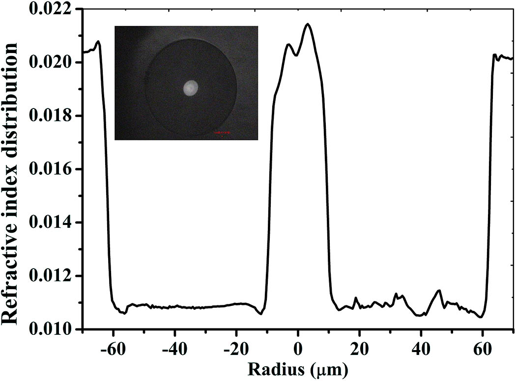
An FM-EDF is fabricated using modified chemical vapor deposition (MCVD) in combination with a liquid solution. The fabrication process can be divided into three steps. First, a porous soot layer is deposited inside silica substrate tube using MCVD technology. During the process, chemical reactions in the gas form a fine soot of silica, which coats the inner surface of the substrate tube and is sintered into a semi-clear soot layer. Second, germanium ions are doped into the fiber core, as optical fiber core layers, and then the erbium ions are doped into the optical fiber core using the liquid solution. A few-mode Er-doped optical fiber preform is formed using MCVD technology and the liquid solution. At last, the preform is finally drawn into fibers with dimensions of an FM-EDF. The refractive index difference is measured by optical fiber analyzer (S14, Photon Kinetics Inc., USA), as shown in Fig. 1.
Sign up for Chinese Optics Letters TOC. Get the latest issue of Chinese Optics Letters delivered right to you!Sign up now
Figure 1.Refractive index distribution and cross-section of the FM-EDF.
The refractive index difference between the core and cladding of the FM-EDF is approximately 0.98%. Their diameters are approximately 19.44 and 124.12 μm, respectively, as shown in Fig. 1. In addition, numerical aperture (NA) is 0.17. The cross section of the optical fiber is also shown in the upper left corner of Fig. 1.
The absorption spectrum of the FM-EDF is measured with the common cut-back method, using a white light source. When we test the on-off gain, we choose a narrow linewidth (100 kHz) continuous-wave tunable laser (Key sight 81600B) with operation range 1530–1600 nm, as the signal light with a wavelength at 1521.2 nm, and a 980 nm laser as the pumping light source. The optical spectrum of the fiber samples is measured using an optical spectrum analyzer (OSA, Yokogawa AQ-6315A). The pump and the signal light are coupled into an FM-EDF using the coupler that is fabricated with the SMF and few-mode fiber (FMF) by an optical fiber conic clinker (OB-612).
For a comparison, the absorption spectrum of a commercial EDF (EDFC-980-HP Nufern Company, USA) is also measured for reference, as shown in Fig. 2. There are five absorption peaks at 485, 643, 787, 968, and 1522 nm, respectively. Those are typical absorption peaks of erbium ions[14–16], which correspond to , , , , , and . The absorption peaks of the FM-EDF are much higher than that of the commercial EDF, mainly due to the difference in the concentration of erbium ions in the fibers, which will make them obtain big differences in gain characteristics[17–20].
Figure 2.Absorption spectra of the FM-EDF and EDF (EDFC-980HP).
For the FM-EDF, according to Eq. (1), the value of the normalized cut-off frequency V at 1550 nm is 6.81, which is a five-mode optical fiber, where is the fiber core diameter; is the wavelength of the signal light; and , are the refractive index of the core and cladding, respectively. According to the parameters of the FM-EDF, the mode characteristics are also simulated with COMSOL software, as shown in Fig. 3. The higher-order mode can be excited using some methods. The , , and modes beam can be transmitted in the FM-EDF. Therefore, the amplification performance of the mode beam can be studied. According to the absorption spectrum, an appropriate pump power, at 980 nm, is selected using the formula
Figure 3.Different modes beam in an FM-EDF: (a) , (b) , and (c) .
An optical amplification system is built up, as shown in Fig. 4. A tunable laser is used as signal light at 1521 nm. The signal light is the fundamental mode observed by the charge-coupled device (CCD, HAMAMATSU C10633). The mode beam of signal can be converted into with an LPFG. The LPFG can be fabricated by several methods including ultraviolet (UV) laser[21], arc technique[22], mechanical microbending[23], laser[24], and so on. Here, because of the advantages of the laser writing technique, the LPFG can be successfully written in various types of specialty fibers by laser, for example, fluid-filled photonic crystal fiber. Therefore, the LPFG that we used in the all-fiber amplification system is written by the laser method, and its conversion efficiency is approximately 99%, which is reported in detail[25]. The mode beam and 980 nm laser are coupled together into the FM-EDF using the homemade coupler.
Figure 4.Schematic diagram of the all-fiber LP mode amplification system.
The FM-EDF is spliced at one end of the coupler and the lens is placed at the end of the FM-EDF. The length of the FM-EDF is 0.8 m. A CCD camera is placed at the end of the experimental system. The results show that mode beam is able to transmit in the entire optical amplification system, as shown in Fig. 4. When we change the pump power, the on-off gain spectrum of the FM-EDF is obtained by the OSA and the beam is observed by the CCD camera.
The signal light and pump power are injected into the FM-EDF with the coupler. The signal power is fixed at 5.47 mW and the pump power is changed from 0 to 300 mW. Here, signal light is offered by broadband light source. The actual injection pump powers are 4.5, 9.3, 19.9, 31.1, and 44.0 mW, respectively, at B point site in Fig. 4. The on-off gain spectra are shown in Fig. 5. When the pump power is only 4.5 mW, the on-off gain of the FM-EDF is 16.04 dB at 1521.2 nm. Then, the injection pump power is up to 44.0 mW, the on-off gain of the FM-EDF is 37.2 dB with the signal wavelength at 1521.2 nm. It can be seen that the on-off gain spectrum of the FM-EDF is increased with the increasing of pump power, as shown in the upper right corner of Fig. 5. Therefore, mode beam can be amplified in the all-fiber amplification system that we design and fabricate.
Figure 5.On-off gain spectra of the FM-EDF with different pump powers.
After making a modification in above all-fiber LP mode amplification system, a first-order OAM is obtained and the experimental system is shown in Fig. 6. A 30:70 fiber coupler and a polarization controller (PC) are used in this experimental system. The PC is used in this all-fiber amplification system to adjust the polarization state of the input fundamental mode (), which can make the mode be converted to a first-order OAM. The combination of the non-polarizing beam splitter (NPBS) and mirror is used to combine the output beam and reference beam. Therefore, this all-fiber amplification system can be used to further study the amplification characteristics of the first-order OAM.
Figure 6.Schematic diagram of an all-fiber OAM amplification system.
It can be observed from Fig. 6 that the first-order OAM beam can be obviously observed at the end of the system. The transverse mode field intensity of the first-order OAM is increased with the increasing of the pump power, and its distribution remains essentially constant, as shown in Fig. 7. Two pictures, which are the transverse mode field distribution and helical interference of first-order OAM, are shown in the upper left of Fig. 7. The curves on the transverse mode field represent the intensity distribution of the first-order OAM in the horizontal and vertical directions. The green and red lines are shown in the upper left of Fig. 7. The other curves show the change in the mode field intensity of the vortex beam at different pump powers. We select the maximum intensity position of the transverse mode field under the different pump powers, respectively. After calculation and analysis, we note that the transverse mode field intensity of the first-order OAM is increased with the increasing of the pump power, as shown in Fig. 8. Those results show that the first-order OAM is amplified.
Figure 7.Variation of the first-order OAM transverse mode field intensity with different pump powers.
In conclusion, we design and fabricate an FM-EDF. Its core and cladding diameters are approximately 19.44 and 124.12 μm, respectively. The refractive index difference between the core and cladding is approximately 0.98% and the NA is 0.17. Then, we build up an all-fiber amplification system to measure and analyze the gain property of the FM-EDF. The on-off gain of the mode is 37.2 dB when the signal power at 1521.2 nm is 5.47 mW. The intensity of first-order OAM is increased with the increasing of the pump power. These show that both the mode and the first-order OAM beams are amplified in the all-fiber amplification system. This kind of FM-EDF is a basis for studying all-fiber OAM amplifier, and this all-fiber OAM amplification system can be applied in the vortex amplifier and laser fields in long distance optical communication systems.
References
[1] G. Gardner. Ward’s Auto World, 33, 60(1997).
[2] R. Ryf, S. Randel, A. H. Gnauck, C. Bolle, R.-J. Essiambre, P. Winzer, D. W. Peckham, A. McCurdy, R. Lingle. National Fiber Optic Engineers Conference, PDPB10(2011).
[10] L. Zhu, J. Li, G. Zhu, L. L. Wang, C. Cai, A. Wang, S. Li, M. Tang, Z. He, Y. Yu, C. Du, W. Luo, J. Liu, J. Du. Optical Fiber Communication Conference, W4C-4(2018).
[11] Y. Luo, W. Zhou, L. Wang, A. Wang, J. Wang. Optical Fiber Communication Conference, M4D.2(2018).
[12] Y. Zhao, Y. Liang, X. Su, W. Zhou, Y. Luo, Z. Huang, J. Wang. Optical Fiber Communications Conference and Exposition, W2A.24(2018).
[13] J. Liu, H. Wang, S. Chen, S. Zheng, L. Zhu, A. Wang, N. Zhou, S. Li, S. Li, C. Du, Q. Mo, J. Wang. Optical Fiber Communication Conference, W2A-21(2017).
[14] P. Wang, J. Wen, Y. Dong, F. Pang, T. Wang, Z. Chen. Asia Communications and Photonics Conference, AW4C.5(2013).
[15] J. Wen, P. Wang, Y. Dong, F. Pang, X. Zeng, Z. Chen, T. Wang. CLEO , JTu4A(2013).
Jianfei Xing, Jianxiang Wen, Jie Wang, Fufei Pang, Zhenyi Chen, Yunqi Liu, Tingyun Wang. All-fiber linear polarization and orbital angular momentum modes amplifier based on few-mode erbium-doped fiber and long period fiber grating[J]. Chinese Optics Letters, 2018, 16(10): 100604