1College of Physics, Optoelectronics and Energy, Soochow University, Suzhou 215006, China
2Key Lab of Advanced Optical Manufacturing Technologies of Jiangsu Province and Key Lab of Modern Optical Technologies of Education Ministry of China, Suzhou 215006, China
3Collaborative Innovation Center of Suzhou Nano Science and Technology, Soochow University, Suzhou 215006, China
Fan Gao, Xiao Yuan, Xiang Zhang. Sidelobes suppression in angular filtering with volume Bragg gratings combination[J]. Chinese Optics Letters, 2016, 14(6): 060502
Copy Citation Text
A method for beam diffraction sidelobe suppression based on the combination of volume Bragg gratings (VBGs) with different thicknesses or periods for angular filtering is proposed and performed. Simulated and experimental results show that the beam diffraction sidelobe is reduced from 12% to less than 1% with the non-sidelobe angular filter. The non-sidelobe angular filtering based on VBGs with thicknesses of 2.5 and 2.9 mm is simulated and demonstrated. The near-field distribution of filtered beams through the non-sidelobe angular filter is obviously smoother than that of the single VBG. The near-field modulation and contrast ratio (C) of filtered beams are found to be improved 1.17 and 1.66 times that of the single VBG. The far-field C of the filtered beam is improved to about and the power spectral density analysis shows that the cutoff frequency of the angular filter is greatly optimized with the VBG combination.
During the development of laser technology, laser media, and optical components, damage has been an important factor affecting the development of high-power laser technology. The improvement of laser beam near-field uniformity was extremely limited by the combined effects of the high-frequency noise in an optical system (such as dust and the defects of the optical components), diffraction, various types of nonlinear effects, etc. Traditional pinhole spatial filtering can inhibit the rapid nonlinear growth and improve the beam near-field uniformity[1]. However, it is still difficult to meet the requirements of a high-power laser device due to many of the inherent defects of the traditional pinhole spatial filter[2–5], such as back-reflection and pinhole-closure. In order to effectively solve the above problems, the angular filtering based on the volume Bragg grating (VBG) was proposed to clean up the medium and high spatial frequencies (MHFs) and improve the near-field beam quality, which can improve the reliability of the laser system and reduce the complexity and cost of the laser system. In 1989, Meltz produced the Bragg gratings in photorefractive germanosilicate fibers by exposing them to a coherent two-beam UV interference pattern[6]. In the 1990s, Sutherland reported the electrically switchable volume gratings in polymer-dispersed liquid crystals (PDLCs). The volume nature of the gratings was confirmed with scanning electron microscopy[7]. Ludman proposed the non-spatial filter[8] based on the angular selectivity of volumeholographic gratings recorded in different photosensitive materials, such as dichromated gelatin, porous glass, and thick photopolymers with diffusion amplification (PDA)[9]. They studied the design and preparation method of volume holographic gratings, and demonstrated the angular selectivity of volume holographic gratings with a divergence beam[10]. In 2004, Volodin utilized the VBG based on the use of inorganic photorefractive glass to stabilize and narrow the spectrum of high-power laser diodes[11]. The glass was based on alumo-sodia-silicated material doped with silver and sensitized by cerium. In 2009, Zheng et al. finished the low-pass non-spatial filtering experiment with VBG based on the photopolymer[12]. In 2011, Zheng reported the experiment on one-dimensional spatial filtering of a deformed laser beam with transmitting VBGs[13]. Photothermorefractive (PTR) glass, developed by Glebov, is used to record VBGs used in angular filtering, due its better thermal stability and damage threshold[14,15]. In our previous research, the angular filtering with VBGs recorded in PTR glass was proposed and performed[16]. Near-field modulation (M) and contrast ratios (C) were used to evaluate the output beam quality of angular filters. The property of spatial frequencies was characterized with the power spectral density (PSD). In the above research, the sidelobes of the angular selectivity seriously affect the filtering performance of the angular filter with VBGs. A few MHFs still remained in the output beam. Wreede et al. proposed using pre-exposure to achieve the sidelobe suppression in holograms[17]. The 8 dB improvement of the sidelobes level in the holographic optical filter in the : Fe crystal was obtained by using weighted grating intensity distribution along beam propagation, but the peak diffraction efficiency decreased two times[18]. The sidelobe suppression in volume holographic optical elements was achieved by using the longitudinal refractive index modulation in photosensitive glasses[19]. These sidelobe suppression methods go against the wavelength selectivity of volume holographic gratings. The suppressing beam diffraction sidelobe method for angular filtering has not been reported.
In this Letter, a method of sidelobe suppression with combined transmitting VBGs was proposed. The principle of the proposed non-sidelobe angular filter and the relevant numerical calculation were described. The non-sidelobe angular filter based on VBGs recorded in PTR glasses with thicknesses of 2.9 and 2.5 mm was demonstrated. The near-field M, near-field C, and PSD were used to evaluate the filtering performance.
The diffraction characteristic of VBGs can be described by the couple-wave theory[20]. The angular selectivity of the transmitting VBG is written as where is the refractive index modulation, is the grating thickness, is the grating period, is the slanted angle of the grating vector, is the wavelength of the incident beam, and and are the angles of the incident and diffracted beams, respectively. is the deviation angle from the Bragg angle.
Sign up for Chinese Optics Letters TOC. Get the latest issue of Chinese Optics Letters delivered right to you!Sign up now
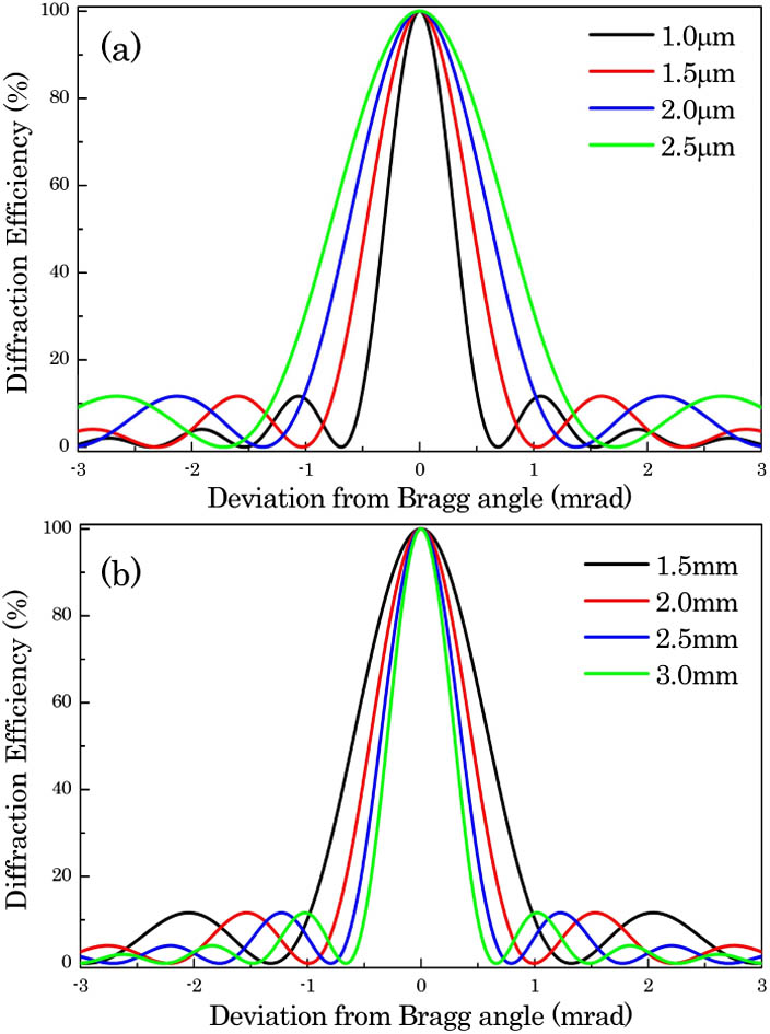
The dependence of the diffraction efficiency and angular selectivity of the VBGs with different grating periods and thicknesses is shown in Fig. 1. The thickness of the VBGs in Fig. 1(a) is 2.0 mm and the grating period of the VBGs in Fig. 1(b) is 1.5 mm. The angular selectivity of a single VBG is sensitive to the grating period and thickness. There are several sidelobes in the angular selectivity, and the maximum efficiency of the sidelobes reach about 12%, which may affect the filtering performance.
Figure 1.Angular selectivities of the VBGs with different (a) grating periods and (b) thicknesses.
The non-sidelobe angular filter is combined of two transmitting VBGs with different angular selectivities. The maximum of the sidelobe in the angular selectivity for one VBG approximately corresponds to the zero point of the sidelobe in the angular selectivity for another VBG, which can be accurately modified with the grating period or thickness. Then, the sidelobes in the angular selectivity for the combined VBGs can be suppressed, which can be used to eliminate the MHFs in the high-power laser system more effectively. As shown in Fig. 2(a), the green and blue curves are the angular selectivities of the VBGs with the period of 2.5 and 3.5 μm, respectively. The thickness and refractive index modulation of two VBGs are 4.0 mm and 66 ppm. The red curve is the angular selectivity of the combined VBGs. The stimulated results show that the diffraction efficiency of the first sidelobe reduces from 12% to 0.5% after the combination. The full width at first zero point (FWFZ) of the combined VBGs is close to that of the VBG with the better angular selectivity. However, the full width at half-maximum (FWHM) of the combined VBGs decreases from 0.76 to 0.62 mrad, which means that the angular bandwidth narrows.
Figure 2.Angular selectivities of the single VBG and combined VBGs with different (a) periods and (b) thicknesses.
The sidelobe suppression can be also achieved with the VBG’s combination with different thicknesses. In Fig. 2(b), the green and blue curves are the angular selectivities of the VBGs with the thicknesses of 2.5 and 2.9 mm, respectively. The refractive index modulations of the two VBGs are 105 and 90 ppm, respectively, and the periods are both 0.96 μm. After the combination, the diffraction efficiency of the first sidelobe reduces from 12% to 1%. Likewise, the FWFZ of the combined VBGs is close to that of the VBG with the better angular selectivity, and the FWHM decreases from 0.34 to 0.28 mrad. The power penalty resulting from the angular bandwidth narrowing can be less than 8% when the maximum of the sidelobe in the angular selectivity for one VBG approximately corresponds to the zero point of the sidelobe in the angular selectivity for another VBG.
The schematic diagram of the angular selectivity demonstration with two combined VBGs was shown in Fig. 3. The laser beam used in the experiment was a continuous wave (CW) frequency-doubled YAG laser with a wavelength of 532 nm and an output power of 2 W. The divergent beam was obtained with a combination of the soft-edged aperture and spatial filter. The focal length of both lenses in the spatial filter was 1000 mm, and the pinhole was 0.5 mm. The distance between the first lens and the pinhole is 1000 mm, and the distance between the pinhole and second lens was 900 mm. Then, the divergent beam after the second lens was incident on the VBG-I at the Bragg angle of 16.2°, and the diffracted beam after the VBG-I was incident on the VBG-II at the same Bragg angle. The parameters of the two VBGs are shown in Table 1. A CCD was used to record the beam profile of the filtered beam here.
Period
Thickness
Refractive Index Modulation
Diffraction Efficiency
VBG-I
0.96 μm
2.9 mm
70–100 ppm
85%
VBG-II
2.5 mm
Table 1. Parameters of the VBGs Used in the Experiment
There were series diffraction sidelobes on both sides of the central peak for the single VBG-I in Fig. 4(a). When the VBG-II inserted, the sidelobes were obviously cleaned up, and the central peak was narrower, as shown in Fig. 4(b). Thus, the non-sidelobe angular filter with the combined VBGs has a better filtering ability than a single VBG.
Figure 4.Near-field beam profile of the diffracted beams through (a) a single VBG-I and (b) the combined VBGs.
The schematic diagram of the non-sidelobe angular filter with the combined VBGs was shown in Fig. 5. The distance between the pinhole and the second lens was 1000 mm. The collimated original beam with the size of was obtained after the second lens. Then, the original beam was deeply modulated by a 1 lp/mm mesh grid and incident on the VBG-I and VBG-II at the Bragg angle of 16.2°.
Figure 5.Schematic diagram of the non-sidelobe angular filter with the combined VBGs.
The near-field M and near-field C were used to evaluate the output beam quality[21], which were defined aswhere is the number of sampling points, is the intensity corresponding to the th point, and is the average intensity of all of the points. The near field , which is defined as the ratio between the maximum peak intensity and the average intensity in the beam flat-top region, reflects the near-field intensity fluctuations. The near-field C is the root mean square (RMS) of the intensity fluctuation in the near field.
The near-field distribution of the modulated beam and diffracted beams through the single VBG-I and the combined VBG-II was shown in Fig. 6. After the angular filter based on a single VBG-I, there were still some obvious spatial Ms in the flat-top region of the diffracted beam. However, after the non-sidelobe angular filter, these spatial Ms can be eliminated effectively.
Figure 6.Near-field distribution of the (a) modulated beam, (b) diffracted beams through single VBG-I, and (c) through combined VBGs.
The corresponding near-field M and C were given in Table 2. The near-field M and C for the angular filtering with the single VBG-I were improved 2 and 11.5 times, respectively. And the near-field M and C for the combined VBGs were improved 2.4 and 19 times, respectively. Therefore, the non-sidelobe angular filter with the combined VBGs has a stronger filtering ability.
The far-field distribution of the diffracted beam also confirmed that the filtering performance of the non-sidelobe angular filter was improved, as shown in Fig. 7. Since the spatial frequencies introduced by the 1 lp/mm mesh grid were not completely cleaned up by the single VBG-I, there were many diffraction sidelobes on both sides of the central focal spot, as shown in Fig. 7(b). These residual spatial frequencies caused by diffraction sidelobes may threaten the stability and security of the high power laser system, which can be effectively eliminated by the non-sidelobe angular filter based on the combined VBGs, as shown in Fig. 7(c). There were no visible sidelobes on the both sides of the central focal spot, and the far-field C is improved to about .
Figure 7.Far-field distribution of (a) modulated beam, (b) diffracted beams through the single VBG-I, and (c) through the combined VBGs.
The above experiments and analysis showed that the non-sidelobe angular filters based on combined VBGs with different parameters have a stronger filtering ability. However, the process of angular filtering cannot be described accurately with these methods, since these methods have some randomness. Therefore, the PSD is used to further analyze and evaluate the output beam through the angular filter. The PSD is an analytical method in the spatial frequency domain, which quantificationally describes the distribution of power in the spatial frequency space and can give a clear description about the process of spatial filtering[22].
Figures 8(a) and 8(b) show the dependence of the PSD with spatial frequency for the original and modulated beams, respectively. There are plenty of spatial frequencies between 1 and . After the angular filter based on a single VBG-I, most of the spatial frequencies greater than or equal to were cleaned up due to the angular selectivity of VBG-I, but the lower spatial frequency of was harder to clear out, as shown in Fig. 8(c). To filter the lower frequency with the angular filter completely, it must suppress the diffraction sidelobes of angular selectivity. As shown in Fig. 8(d), the lower spatial frequency of was completely cleaned up by the non-sidelobe angular filter based on the combined VBGs. There were no obvious spatial frequencies in the MHF M in the region of 1 to . Therefore, the cutoff frequency of the angular filtering was optimized by the combined VBGs with different thickness.
Figure 8.Dependence of the PSD with spatial frequency for (a) original beam, (b) modulated beam, (c) filtered beam through the angular filter based on the single VBG-I, and (d) filtered beam through the non-sidelobe angular filter.
In conclusion, the combined VBGs with different thicknesses or periods is a simple and practicable method to suppress the beam diffraction sidelobes, and can effectively improve the filtering performance of the angular filter based on the VBGs. Numerical simulation shows that the diffraction sidelobes can be reduced to less than 1% with the combined VBGs of different thicknesses or periods. The non-sidelobe angular filtering based on the combined VBGs with thicknesses of 2.5 and 2.9 mm is simulated and experimentally demonstrated. The near-field distribution of the filtered beam through the non-sidelobe angular filter is smoother than that of the single VBG. The near-field M and C of filtered beams through the non-sidelobe angular filters are found to be improved 1.17 and 1.66 times that of the single VBG and the MHF is effectively eliminated. The far-field C of the filtered beam is effectively improved with the non-sidelobe angular filter. The PSD curves show that the cutoff frequency of angular filter is greatly optimized with the non-sidelobe angular filter.