Jiangsu Key Laboratory of Advanced Laser Materials and Devices, School of Physics and Electronic Engineering, Jiangsu Normal University, Xuzhou 221116, China
We studied Goos–H nchen (GH) shifts on a reflective phase-gradient-produced metasurface. Their analytical solutions were achieved for both TE and TM polarizations utilizing the generalized Snell’s law. The calculated results show that the GH shifts are evidently affected by phase gradients and incident angles, which means that a certain range of GH shifts can be realized as long as an incident angle, phase gradient, and frequency are properly chosen. This offers an effective method for the control of GH shifts.
When total internal reflection occurs at the interface between two media with different refractive indexes, the reflected beam will shift a lateral displacement in the wavelength scale relative to the position of incidence. This displacement phenomenon was indirectly described by Newton and then demonstrated experimentally by Goos and Hänchen[1,2]. The evanescent field in the low refractive index medium leads to a phase change between the reflected and incident beams, which finally brings the Goos–Hänchen (GH) shift. It is the consequence of interaction between the beams and the interface. The effect of the GH shift is not generally conspicuous after one or several reflections in traditional optical tools, but it will become strong through multiple reflections in optical wave guides[3]. About a decade ago, the GH shift attracted interest of researchers again due to proposed metamaterials and surface plasmon structures with novel properties. The anomalous indexes of the metamaterials from plasmon resonances can cause extraordinary effects on the GH shift. The interface of two different handed metamaterials will result in a negative lateral GH shift[4–7]. It can also use surface plasmon resonances[8] or the role of interfering localized plasmon modes[9] to obtain giant GH shifts. Besides, transformation optics for surface phenomena can be utilized to engineer GH shifts[10]. In recent years, metasurfaces have been developed from metamaterials with one dimensionality reduced. The metasurfaces, generally consisting of sub-wavelength metal patterns with certain phase responses, are capable of building artificial phase gradients along the interfaces between two different media. In the metasurfaces, the generalized Snell’s law[11] is often introduced to describe how they affect phases of light during propagation. It is reported that metasurfaces have many potential applications in realizing holograms[12,13], polarization transition[14,15], metalenses[16], etc.[17,18]. However, the GH shift as an important property during light propagation was not investigated in metasurfaces too much. Yallapragada et al. reported the observation of giant GH and angular shift on polymethyl methacrylate grating metasurfaces attached on the upper side of metal. The condition of incident light in this article is from air to metal, which is quite different from the conventional cases of total internal reflection[19]. Farmani et al. focused on the tunable GH shift based on the graphene contained metasurfaces, and they achieved pretty good gains[20,21]. In this Letter, we will discuss how the GH shifts change when the total internal reflection occurs at the interface covered by a reflective phase-gradient metasurface, which has some differences from the systems reported above. Analytical solutions and the corresponding calculation results show that the GH shifts are obviously affected with the changes of phase gradients and incident angles. This indicates that we can artificially control the GH shifts by designing a proper metasurface on a total internal reflection interface.
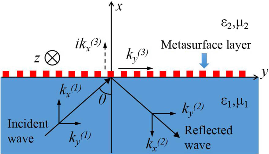
Here, we use a similar method to that in Ref. [5] to analyze the mechanism of GH shift in a reflective phase-gradient metasurface. As is shown in Fig. 1, in which a coordinate system is drawn, two common media are divided by the metasurface.
Figure 1.Schematic of an electromagnetic wave totally reflected at the interface between two media. The axis is perpendicular to the interface, and the axis is parallel to the interface. A metasurface is attached on the upper side of medium 1.
The half-space for is filled with medium 1, and the half-space for is filled with medium 2. Here, we consider that their permittivities and permeabilities are both positive. We assume that the metasurface has a phase gradient of , in which denotes the phase in it. Because the thickness of the metasurface is much smaller than the wavelength of incidence, the effects in it along the normal direction can be ignored, and only the response of the phase gradient along the interface needs to be considered. To understand the effect of the phase gradient, we first take a TE polarized wave incidence as an example. The TE polarized wave comes from medium 1 with an incident angle of . The electric fields in two media can then be expressed as follows: where , , , , , , , , , , and in the two equations represent the amplitude of the incident wave, the angular frequency, the reflection coefficient, the transmission coefficient, the time, the wave vector of the incident wave in , the wave vector of the incident wave in , the wave vector of the reflected wave in , the wave vector of the reflected wave in , the wave vector of the refracted wave in , and the wave vector of the refracted wave in directions, respectively. The components of the wave vectors in the two media in Fig. 1 have the relationships of , , and , where , , , and denote the permittivities of media 1 and 2, and the permeabilities of media 1 and 2, respectively. The in-plane wave vectors satisfy a conservation relationship of . However, when the interface is designed with a phase gradient, the component of the incident wave vector will go through a phase shift. The resulting vector can be expressed as . The phase-shift response caused by a metasurface will occur in both the reflection[22] as well as transmission[11]. The most common way to design a phase-gradient metasurface is by utilizing the sub-wavelength metal antennas. A unit cell consists of an antenna, whose reflection or transmission phase response to a frequency is determined by the components, shapes, and orientations of the antenna. The phase responses of the units should be designed in the range from 0 to with equal separations, such as , and . When the units are arranged in the order of the phase response and with an equal space, unit arrays with certain periodicity will form. Then, the phase gradient of this metasurface can be achieved by . As a result, the original conservation among the in-plane wave vectors will be broken and should be rewritten as follows:
Sign up for Chinese Optics Letters TOC. Get the latest issue of Chinese Optics Letters delivered right to you!Sign up now
Accordingly, the relationships of components in every part of propagation will also be changed to , , and . Considering the optical thin feature of the metasurface, the boundary conditions for the electric and magnetic fields will not be affected by the metasurface in the surface normal direction. Thus, the following relations can be obtained: and
Using the relationship of wave vector components and substituting related components into the two equations above, we can achieve the reflection coefficient, where and denote the amplitude and phase of the reflection coefficient. Although the form of is the same as that derived from general boundary conditions in Ref. [5], the components of wave vectors are affected by , which contains a phase gradient. When the total internal reflection occurs, the new components of wave vectors still obey . That is, becomes a pure imaginary number. Another constraint condition is given by the generalized Snell’s law[11], and the critical angle for the total internal reflection is
Following this relationship, we plotted the critical angles as functions of for three different frequencies. The corresponding results are shown in Fig. 2. The parameters , [23], and are set in the caption of Fig. 2. From this figure, we can find that if the total internal reflection occurs, the incident angle should be set larger than the critical angle . Hence, the incident angle should locate at regions I and III in Fig. 2.
Figure 2.Critical angles as functions of the phase gradient in the direction for 30, 40, and 50 THz incident waves. and − represent the cases for ‘’ and ‘’ in Eq. (7), respectively. The refractive index of medium 1 considered as silicon was set approximately to [23], and medium 2 was regarded as the vacuum ().
Once the condition for total internal reflection is satisfied, the GH phase shift , can be obtained from Eq. (6). For simplicity, the phase gradient is known as a constant of . We can then yield by utilizing Artman’s equation[24], in which . Therefore, the GH shift in the phase-gradient metasurface for TE polarization is which is similar to that in Ref. [5]. With a similar method, the GH shift in this kind of metasurface for TM polarization can also be achieved as follows:
To clearly illustrate the influence brought by the phase gradient on GH shifts, we plotted the GH shifts as functions of the phase gradient for two polarizations. In calculations, the incident angle is equal to 60°, which meets the condition of total internal reflection. The other parameters are the same as those in the caption in Fig. 2. The GH shift curves for both TE and TM polarizations at three given frequencies are shown in Fig. 3.
Figure 3.GH shifts on the phase-gradient metasurface as functions of the phase gradient at 30, 40, and 50 THz frequencies for the (a) TE and (b) TM polarizations.
Figure 3(a) shows that the GH shifts decrease when the phase gradient rises for the three frequencies. The GH shifts descend more evidently in value for the lower frequencies. The GH shift for 30 THz becomes infinite at about phase gradient. The reason is that the factor in Eq. (8) tends to zero at the phase gradient. For 40 and 50 THz, similar phenomena also occur in the range of less than phase gradients, which is not plotted in Fig. 3(a). The TM case is similar to the TE one, as shown in Fig. 3(b). The GH shifts also decrease with the increase of phase gradient for the three frequencies and become infinite at the lower phase gradients. Differently, the GH shifts for the TM polarization are smaller than those for the TE polarization for the same frequencies. From Fig. 3, we also find that the GH shifts in the range of negative phase gradients drop more swiftly than those in the range of positive phase gradients. As a result, by adjusting the phase gradients of metasurfaces, which can be realized by altering their sizes and shapes, we can manipulate the GH shifts.
Next, we will discuss the changing ratio of the GH shifts brought by the varied phase gradients. A dip ratio is thus defined as follows: where and are the GH shifts with phase gradients and without phase gradients, respectively. Following this definition, the dip ratios for the TE and TM cases were available by using the data from Fig. 3. The corresponding curves are plotted in Fig. 4.
Figure 4.Dip ratios as functions of the phase gradient at 30, 40, and 50 THz frequencies for the (a) TE and (b) TM polarizations.
The trends of dip ratios are similar to the corresponding curves in Fig 3. In Fig 4, the horizontal dash line represents the GH shift at the silicon-vacuum interface without a metasurface. Evidently, the metasurface resulting in phase gradients has a great influence on the GH shift. Comparing Fig. 4(a) with Fig. 4(b), we can see that the effects of the phase gradient on GH shifts under the TM polarization are more efficient than that under the TE polarization. For example, when the phase gradient is , the dip ratio is 150%, which indicates that the GH shift increases by 1.5 times relative to the one without a metasurface for the 30 THz wave under the TM polarization, while it increases only by approximately 50% under the TE polarization.
The GH shifts are also related to incident angles; we therefore plotted GH shifts as functions of incident angles for the two polarizations at the frequency of 40 THz, as shown in Fig. 5. From this figure, it can be found that the GH shifts are obviously affected by the incident angles. Furthermore, the GH shifts for different phase gradients change differently in degree with increasing incident angles. This indicates that a certain range of GH shifts can be realized as long as an incident angle and a phase gradient are properly chosen.
Figure 5.GH shifts as functions of the incident angle for the different phase gradients () of , , 0, , and at the frequency of 40 THz. (a) TE polarization; (b) TM polarization.
The discussions above are based on double positive materials, and the metasurface embedded in them gives rise to a constant phase gradient in one direction. Actually, the analytical solution is still effective for double negative materials or one negative and one positive material. For instance, if medium 1 is a double negative medium and medium 2 is a double positive one, that is , , , and , the GH shifts following Eqs. (8) and (9) will become negative. The negative GH shifts indicate the shift direction is opposite to the component of the incident wave vector, which is parallel to the interface. Such negative GH shifts can also be modified by the phase gradient (). However, it does not work when the phase gradient is a function of the position, which means that Eqs. (8) and (9) cannot be met.
In summary, GH shifts at the interface with a reflective phase-gradient-produced metasurface have been investigated. Analytical solutions for GH shifts with phase gradients are given for TE and TM polarizations. It is found that the GH shifts are obviously affected by phase gradients and incident angles. It indicates that a certain range of GH shifts can be obtained as long as an incident angle, a phase gradient, and a frequency are properly chosen. Such a method has potential applications in the control of GH shifts.
[12] L. L. Huang, X. Z. Chen, H. Mühlenbernd, H. Zhang, S. M. Chen, B. F. Bai, Q. F. Tan, G. F. Jin, K. W. Cheah, C. W. Qiu, J. Li, T. Zentgraf, S. Zhang. Nat. Commun., 4, 2808(2013).