A novel H-plane cross-shaped circulator based on magneto-photonic crystals is experimentally investigated. The band gap of the TE mode for the photonic crystals is calculated by the plane wave expansion method. The transmission characteristics of the circulator are simulated by the finite element method. We perform the experiments in the microwave regime to validate the numerical results. At the central frequency of 10.15 GHz, the measured isolation and insertion loss of the circulator reaches and , respectively. The bandwidth of the circulator is about 550 MHz. The optimal experimental value of isolation is higher than the numerical value.
Photonic crystals (PCs)[1,2], also known as photonic band gap (PBG) structures and have gained worldwide interest during the past decades, are periodic structures belonging to a new type of artificial materials that allow people to manipulate the flow of light. Due to the unique characteristics of PCs, such as PBG, photonic localization, and surface states, many devices have been fabricated based on the PCs’ structures[3–12].
Circulators suppress multiple reflections between components and thereby improve tolerance with respect to fabrication imperfections and environmental fluctuations. In recent years, several kinds of two-dimensional (2D) magneto-PC (MPC) circulators are numerically studied[13–15]. However, to the best of our knowledge, the fabrication of an MPC circulator is barely reported. Consequently, it is worth paying attention to experimentally validating the MPC circulator.
In our previous work, a compact PC defect structure is provided to realize cross-shaped waveguide with an ultra-wide bandwidth[16]. Based on the waveguide junction of Ref. [16], a new H-plane cross-shaped MPC circulator is envisaged and is first experimentally developed in the microwave regime in this Letter.
Sign up for Chinese Optics Letters TOC. Get the latest issue of Chinese Optics Letters delivered right to you!Sign up now
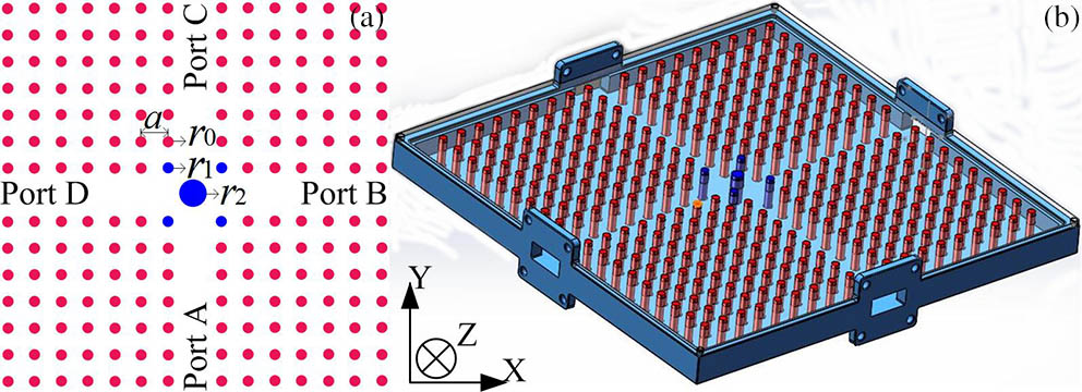
The MPC circulator is composed by putting a nonreciprocal sample at the central point of the cross-shaped waveguide’s junction, as shown in Fig. 1(a). The MPCs are formed by introducing five gyrotropic Ni-Zn ferrite cylinders in the center of the square lattice PCs (SLPCs). The ferrite cylinder with the bigger radius is labeled in blue. Under the external direct current (DC) magnetic field, not only does the ferrite cylinder play the role of a resonator, but it also provides a 90° Faraday rotation angle. In order to improve the isolation of the circulator, four auxiliary rotation ferrite rods (blue) with smaller radius are inserted in the SLPCs (red) around the central ferrite cylinder. The lattice constant of the PCs is . The rods’ radius is with relative permittivity . In the partially transparent rectangular waveguide, the rods of the MPCs are fixed on the upper and bottom plates, as shown in Fig. 1(b). At the end of the waveguide, four Flange interfaces () are designed to connect the test equipment.
Figure 1.(Color online) (a) Structure of 2D MPC circulator with ferrite posts; (b) schematic diagram of the H-plane circulator.
By using commercially available photonic band calculation software (BandSOLVE, Rsoft Design Group), the band structure of the 2D PCs is simulated with the plane wave expansion method. The numerical analysis is carried out here for only TE polarization. As shown in Fig. 2, there is an ultra-wide PBG in the SLPCs with the normalized frequency range of . The numerical central frequency of the PBG is . By calculating with the light speed , the frequency range of the PBG is 8.81–11.72 GHz, and the central frequency is 10.04 GHz. In principle, PCs forbid the propagation of electromagnetic waves within the PBG frequency range and reflects impinging electromagnetic waves back.
Figure 2.(Color online) TE band structures of the SLPCs.
The authors have performed experiments to validate the PBG of the SLPCs. The experimental results perfectly agree with the numerical results[17]. Furthermore, a cross-shaped PC waveguide is developed based on the PBG[16]. The experimental results show that the electromagnetic wave can be transmitted stably in the waveguide within the frequency range of the PBG. The transmission efficiency of the waveguide is shown in Fig. 3. If some nonreciprocal sample, such as a ferrite post biased external magnet, is put in the central point of the waveguide’s junction, a circulator can be realized in the frequency range of the PBG and is reported in this Letter.
Figure 3.Transmission efficiency of the cross-shaped waveguide.
For a gyrotropic ferrite sample magnetized in the direction in the microwave[18] and terahertz[19,20] bands, the gyromagnetic characteristic of magneto-optical material can be expressed as the permeability tensor in the Cartesian coordinate system: where the symbol of off-diagonal element is decided by the direction of the external DC magnetic field, and the strength of Faraday gyromagnetic effect is measured by the quality factor .
The elements of the permeability tensor are expressed as follows: where is the precession frequency, and is the circular frequency of the incident wave; the gyromagnetic ratio is , is the bias magnetic field, and is the saturation magnetization.
Traditionally, the frequency range of a circulator and its central frequency is determined by solving the tensor Maxwell’s equation in ferrite under a given magnetic bias with the given boundary conditions. Owing to the complexity of the permeability tensor given in Eq. (1), the equations involved are extremely complex. It is doubtful whether the equations can be solved in a closed form. For a waveguide Y-junction circulator with a ferrite cylinder, Owen[21] showed that the central frequency of the circulator was approximately equal to the resonant frequency of the ferrite cylinder, as if the latter were treated as a dielectric resonator. Following this theory, the ferrite cylinder is first examined as a dielectric resonator in PC waveguide’s junction, as shown in Fig. 4(b). A simple formula is derived to determine the central frequency of a magnetized ferrite cylinder[22], in which the relationship between the radius and height of the ferrite cylinder is given: where is the central frequency of the MPC circulator. While is the relative permittivity of the Ni-Zn ferrite, is the height of the central ferrite with radius , is a compromise value[22], which ensures that the size of the ferrite cylinder is suitable for the junction of the circulator, is equal to 2.4 here. In that way, the ferrite cylinder is designed first based on the given central frequency. Since the optimal transmission efficiency of the PC waveguide reaches 72% () at the frequency of 10 GHz, the central frequency of the circulator is chosen to be 10 GHz. The height of the central ferrite cylinder is calculated to be 8.13 mm with the radius .
Before experimentally validating the MPC circulator, the external properties of the MPC circulator are simulated at the frequency of 10 GHz by the finite element method (Comsol Multiphysics). The external DC magnetic field is biased along the direction on the ferrite posts, and the quality factor =1.0702. The calculated region is divided into about 112,000 grid cells and is encircled by perfectly matched layers (PMLs) with double lattice constant thickness. In Fig. 5, Ports A, B, C, and D represent the four ports of the circulator. Under the external magnetic field, the propagation direction of the electromagnetic wave has a 90° deflection to realize 90° circulation. Therefore, the electromagnetic wave launched from Port A is almost totally transmitted to Port B (the output port); Port C and D are isolated.
The external characteristic parameters of the circulator are investigated by changing the frequency of the incident electromagnetic wave. When the signal is launched from one of the four ports (Ports A, B, C, and D), we gather the energy of the signal at the other three ports and calculate the isolation and insertion loss of the circulator. The variations of the insertion loss and isolation with frequency for the MPC circulator are shown in Fig. 5. At the central frequency of 10 GHz, the isolation reaches , and the insertion loss is . When the frequency diverges from the central frequency, the transmission characteristics of the circulator deteriorate gradually with an increasing frequency offset.
Figure 4.(Color online) (a) Top view of the MPC circulator; (b) experimental setup for measuring the transmission characteristics of the MPC circulator.
Shown in Fig. 4(a) is the top view of the MPC circulator sample. The experimental setup for measuring the transmission characteristics of the MPC circulator is shown in Fig. 4(b). The circulator and the vector network analyzer are connected through a SubMiniature version A (SMA) connector and waveguide to coaxial converter. Under the action of a permanent magnet (NdFeB), the transmission characteristics of the MPC circulator are measured at the frequency range of 9.5 to 11.5 GHz, as shown in Fig. 6.
Figure 5.(Color online) Numerical variations of isolation and insertion loss with the frequency of the MPC circulator.
In the experiments, the parameter represents the logarithmic value of the ratio of the transmission power of Port 2 from the input port power of Port 1. Similarly, represents the transmission characteristic of Port 2 to Port 1. In the classical measurement of the network analyzer, the S parameters are, respectively, expressed as follows: where and are the input power of Ports 1 and 2. is the transmission power from Port 1 to Port 2, and is the transmission power from Port 2 to Port 1.
In Fig. 5(b), Ports 1 and 2 of the vector network analyzer are connected with Ports A and B of the circulator. Ports C and D of the circulator are connected with the matched load. When the insertion loss of the electric cable and adapter is ignored, the isolation and insertion loss of the circulator are expressed as follows, respectively:
When electromagnetic wave launched from Port A is almost totally transmitted to Port B (the output port), isolating Ports C and D are isolated. At the central frequency of 10.15 GHz, the measured insertion loss of the circulator from Port A to Port B is , the isolations of Ports C and D to Port A are and , respectively, and the bandwidth is about 550 MHz (), as shown in Fig. 6. Comparing with the numerical results, the experimental central frequency of 10.15 GHz takes place with a slightly blue shift. The possible reason is the machining error of the ferrite post. Since the absorbing materials are used on the rectangular edges of the circulator, the experimental insertion loss is higher than the numerical value. On the other hand, the optimal isolation of is better than the numerical results in this Letter. In some points of view, the experimental results agree well with the numerical results mentioned above.
In conclusion, a novel H-plane cross-shaped MPC circulator is designed by using Ni-Zn ferrite posts and SLPCs. The crystals formed by the ceramic rods array have an ultra-wide PBG of 8.81–11.72 GHz, and the relative bandwidth is 29.1%. The central frequency of the circulator is determined basically by the height and radius of central ferrite resonator. Actually, there is a variation of the electromagnetic field along the axis. In this situation, the modeling of the whole structure should be three-dimensional (3D), and the effect of air spacer in the direction should be taken into account. In this way, some error appears. That is a problem for future discussion. The MPC circulator is first developed at the frequency range of 10.15 GHz. The excellent performance of the circulator demonstrates that 2D MPCs are a feasible method for developing nonreciprocal devices in the microwave and millimeter waves.