Abstract
We present a lamp-pumped Nd: phosphate glass laser amplifier delivering up to 1 J of pulse energy at 1053 nm with a repetition rate of 1 Hz and an injected pulse energy of 2.5 mJ. The amplifier system employs a beam-shaping module and a four-pass, lamp-pumped amplifier. The thermally induced wavefront distortion is mitigated and a uniform gain distribution is obtained by a four-lamp-pumped laser head in the amplifier. Thus, an excellent beam quality is obtained.Nd: phosphate glass has good optical homogeneity, a high doping concentration, a suitable stimulated emission cross section (), a broad gain bandwidth (more than 20 nm), and a relatively small nonlinear index. The suitable stimulated emission cross section makes Nd: phosphate glass have large stored energy and efficient energy extraction. In addition, the development of continuous melting makes it possible to massively produce the glass with a large size and excellent optical quality. Thus, it is the best medium for inertial confinement fusion (ICF) lasers, such as the Sheng Guang series, the National Ignition Facility (NIF), and the Megajoule[1]. Such a laser system usually has hundreds of laser beams, and beam alignment and crystal tuning are tough tasks. Most of the tasks are highly automated, and the repetition rate of the probe beam limits the alignment speed. In NIF, for each experiment, the laser beams are aligned from the pre-amplifier modules through the main laser in the laser bays and onto the target using the target alignment sensor. Full alignment of all laser systems to the target chamber center takes almost 1 h[2]. Adding an operation repetition rate of the preamplifier is an effective way to increase the operation efficiency of ICF lasers.
However, the pre-amplifiers of NIF and other similar systems fire at a low frequency, usually several tens of minutes per shoot[3,4]. Under such conditions, the thermally induced wavefront distortion in the gain medium can be ignored. With the increase of the repetition rate, the thermal effect in the gain medium becomes severe. However, Nd: phosphate glass has a low heat transfer coefficient (N31, for example ) and a small fracture toughness[5,6]. It is usually recommended to use a gain medium, which has a relatively high heat transfer coefficient and a relatively large fracture toughness, like NAP2, in high average power systems[1]. Diode pumping is an effective way to mitigate the thermal effect. A laser diode array side-pumped Nd: glass square rod amplifier is reported in Ref. [7], and the output energy reaches 1.62 J under the condition of a 1-Hz repetition frequency. However, owing to the low small signal gain per pass, this amplifier needs a seed energy as high as 50 mJ. Although diode pumping has developed rapidly since 1990 and the price per watt has decreased dramatically, compared to lamp pumping, it is still very expensive.
In this Letter, an Nd: phosphate glass amplifier system is developed to deliver 1 J of pulse energy with excellent beam quality at 1 Hz. The amplifier system contains 2 parts: a beam-shaping module (BSM) and a four-pass, lamp-pumped amplifier. The seed laser is a diode-pumped regenerative amplifier with an all-fiber-based seeder. The all-fiber-based seeder can provide a 1-nJ seed laser. After the regenerative amplifier, the pulse energy reaches 10 mJ. After the BSM, the pulse energy is . The four-pass amplifier needs a gain of to achieve 1 J pulse energy. The severe thermal effects in the gain medium make it very challenging to develop such a laser system. In our system, the thermal effects are minimized, and the wavefront distortion and the birefringence induced by it are carefully compensated for. So, an excellent beam quality is obtained. Under the condition of a 1-Hz repetition frequency, 2.5-mJ injected seed energy, and a aperture, the output energy of the laser beam reaches 1 J at 1053 nm. The beam profile is a top hat, and the intensity distribution in the near field is uniform. More than 95% of the energy is in 720 μrad, which corresponds to 2.3 times of the diffraction limit expected for a square 6-order-super-Gaussian beam.
Sign up for Chinese Optics Letters TOC. Get the latest issue of Chinese Optics Letters delivered right to you!Sign up now
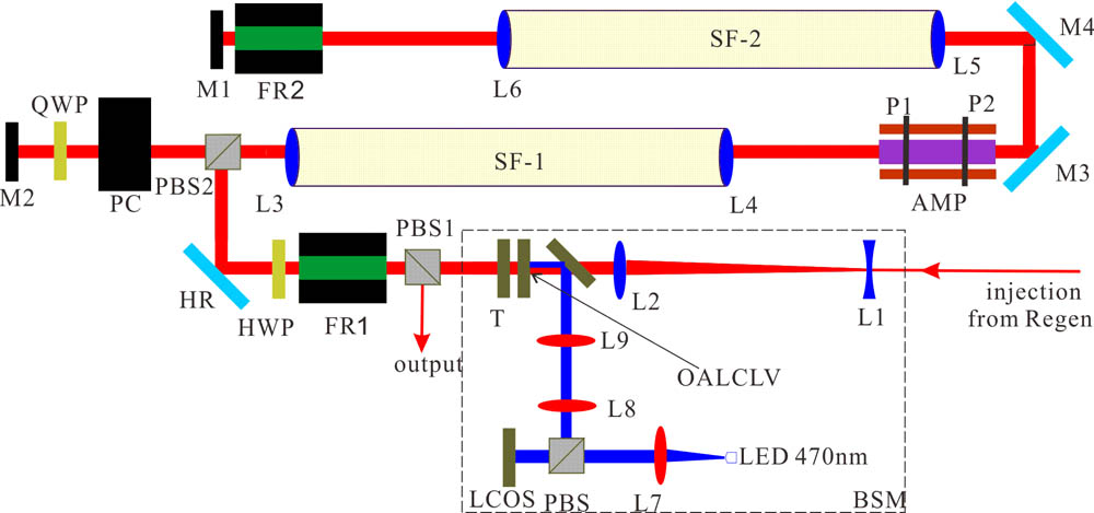
The experimental setup is depicted in Fig. 1. It contains two parts, the BSM and the four-pass amplifier. The BSM contains a beam-expander (L1 , L2 ), a aperture (T), a dichroic mirror (DM), a commercial liquid crystal on silicon (LCOS), a collimated 470 nm light source (L7 and LED), a polarized beam splitter (PBS of 470 nm), an imaging system (L8 and L9), and a homemade optically addressed liquid crystal light valve (OALCLV)[8]. The four-pass amplifier includes two vacuum spatial filters (SF1, SF2 with L3, L4, L5, and L6), a four-lamp-pumped Nd: phosphate glass laser head (AMP), two 15 mm Faraday rotators (FR1, FR2), two polarized beam splitters (PBS1, PBS2), two 45° reflectors (M3, M4), and two 0° mirrors (M1, M2).

Figure 1.Four-pass amplification optical layout.
In the BSM, the beam from the regenerative amplifier is expanded (). Then, the expanded beam passes through the aperture and the OALCLV. The polarization of the read beam (the seed laser) after the valve has a corresponding relationship with the intensity of the 470-nm address beam, which is modulated by the LCOS. The OALCLV have a resolution of 10 lp/mm. The combination of the OALCLV and PBS1 can modulate the intensity distribution flexibly to pre-compensate for the inhomogeneity of the gain in the laser rod. The contrast of the OALCLV is relatively low[8,9]. Therefore, the aperture is added to shape a steep-edge, flat-top laser beam and provide a high contrast. The aperture is attached to the OALCLV to minimize the diffraction effect. Compared other beam-shaping technologies like LCOS, OALCLV has the advantage of high transmittance and overcomes the problem of the black matrix effect.
The coaxial four-pass amplifier is designed to meet the image relaying relation for better beam quality. The OALCLV is the original image plane, which is relayed to the first principal plane of the rod (P1). The second principal plane (P2) is relayed in M1 and P1 is relayed in M2. The distance from P1 and P2 to the near end of the rod is , where and represent the rod length and the refractive index[10]. The linearly polarized beam from the BSM transmits the PBS1, FR1, and half-wave plate (HWP), and the beam polarization rotates 90°. The beam is reflected by PBS2 and goes to the amplifier for the first-pass amplification. Then, the beam is reflected by M1 and the second-pass amplification occurs. The polarization rotates another 90° after two passes through FR2. Then the beam transmits from the PBS2 and is reflected by M2. After that, the third-pass and fourth-pass amplifications follow. The polarization rotates 90° again after another two passes through FR2 and the beam is reflected by PBS2. After the beam transmits from FR1 and HWP, the polarization remains. At last, the beam is reflected by the PBS1 and leaves the amplifier. The Pockels cell (PC) is switched on by a voltage before the laser pulse comes. The polarization remains when the laser pulse transmits the PC and QWP. The dumping time of the PC is as short as 60 ns to block the residual reflectivity and the post-pulse.
The severe thermally induced effect in the gain medium is the first concern. Lamp pumping is an effective way to achieve a high gain. But the emitting spectrum of the lamp does not match the absorption spectrum of the Nd: phosphate glass and contains ultraviolet radiation. The thermal effect of the gain medium is critical at the repetition of 1 Hz. To minimize the thermal effect, we use two methods. First, the spectrum of the pumping light is filtered by a glass tube developed by Shanghai Institute of Optics and Fine Mechanics, which blocks wavelengths shorter than 530 nm. Figure 2 shows the relationships between the pump power and the logarithm of the gain factor and the wavefront distortion for two types of Nd: phosphate glass. The gain medium is a rod () with a doping concentration of 1.2% (atomic percentage), and the pumping cavity used in test is a two-lamp, ceramic, diffuse reflector. It shows that the pumping efficiency with the filter reduces to 75% but the wavefront distortion reduces to 35%, compared to the one without the filter. Secondly, we replace the gain medium by N31. The thermally induced wavefront distortion in NAP2 is much more severe, due to the large temperature coefficient of the optical path (). Compared to NAP2, N31 has a small temperature coefficient of the optical path ()[6]; hence, the wavefront distortion is small. The effective pumping length of the rod increases to 200 mm to reduce the maximum power per unit length dissipated as heat in the rod and guarantee the rod works in a safe region. Figure 2 shows that the wavefront distortion reduces to 22% with the same pump power by changing the gain medium. At first, we choose NAP2 as the gain medium, but the depolarization is difficult to compensate for, due to the large wavefront distortion. The situation improves after replacing the gain medium with N31.
Figure 2.(a) Gain coefficient (logarithm of the gain factor) vs. the pump power with and without the filter for N31 and NAP2. (b) Peak value (PV) of wavefront distortion vs. the pump power with and without the filter.
To obtain a good beam quality, the gain distribution over the cross section of the gain medium should be uniform. The gain distribution has two effects on the beam quality. On one hand, a nonuniform gain distribution results in changes of the intensity distribution in the near field, which increases the spatial intensity modulation. On the other hand, thermal effects in the gain medium cannot be ignored when the frequency increases. A uniform energy density indicates that the heat density is uniform. Hence, the thermal-induced wavefront distortion has a parabolic profile, which can be regarded as a lens and compensated for easily. A nonuniform energy density distribution results in high-order distortions, which are difficult to compensate for and decrease the beam quality. In multi-pass amplifiers, these effects become worse. The rod is pumped by four lamps () symmetrically with diffusive ceramic reflectors, and the doping concentration (1.2%) of the N31 rod is carefully selected to achieve a uniform gain distribution. The beam from the regenerative amplifier is expanded and collimated as a probe laser to measure the gain distribution shown in Fig. 3. The gain factor per pass reaches 6.5 times.
Figure 3.Gain distribution over the cross section of the rod.
The thermally induced wavefront distortions in cylindrical laser rods contain thermal lensing, thermal birefringence, and high-order wavefront distortions[11]. In this amplifier, the high-order distortions are minimized by the uniform pumping. The wavefront distribution obtained by a wavefront sensor (SID4 from Phasics) is shown in Figs. 4(a) and 4(b) when the gain factor per pass is 6.5. Due to the stress-induced birefringence, the wavefront distribution is asymmetrical. In Figs. 4(b) and 4(c), the dashed and solid lines show the wavefront distribution along the vertical and the horizontal lines, respectively. In the experiment, the probe beam is vertically polarized, and the wavefront distributions along the vertical and horizontal axes of the beam are directly related to the radial and tangential polarization components, respectively. In Fig. 4(c), the second-order component of the wavefront distortion (thermal lensing) is subtracted, and it shows the high-order distortions are less than within 90% of the aperture.
Figure 4.(a) Wavefront distribution. (b) Wavefront distribution in horizontal and vertical lines. (c) Wavefront distribution of the high-order distortion in horizontal and vertical lines.
Figure 5 shows the compensation scheme, which is refined from that used in Ref. [10]. The basic idea of the compensation is the simultaneous use of an in-cavity polarization rotator and an imaging optical system between the two passes through the laser rod. The heated rod can be treated as a thick lens with two kinds of focal lengths (). and represent the focal lengths for radially and tangentially polarized radiation, respectively. The beam polarization rotates 90° after two passes through the Faraday rotator to compensate for the thermal-induced birefringence of the rod. To obtain complete compensation for the birefringence, the second principal plane of the rod (P2) is imaged on itself by two passes through L5, L6, and M1. The distance between L5 and L6 is finely adjusted to compensate for the thermal lensing. Here, .
Figure 5.Principle of the thermally induced birefringence compensation.
One of the challenges is to suppress parasitic oscillation. We find two kinds of parasitic oscillation in the experiment. One is caused by the residual reflectivity of optics, such as PBS, laser rod, lenses, and vacuum tube windows. The residual reflectivity of optics is 0.2%, typically. In the four-pass structure, the maximum gain is , which causes parasitic oscillation easily. The rod and the PBS both have a wedge angle of 2°; meanwhile, the lenses and windows are tilted to suppress parasitic oscillation. The tilt orientations of the lenses are strategically chosen to minimize net wavefront distortions. The other one is caused by the depolarization. Once the depolarization is more than , the gain exceeds the losses and parasitic oscillation happens. Although most of the birefringence is compensated for by passing the rod twice through the Faraday rotator and the total depolarization is less than 0.5%, parasitic lasing caused by depolarization still appears. The gain near the edge of the rod is higher than the center, and the heat generated per unit volume near the edge is more than that in the center. This leads to a shorter focal length than the thermal lens. The amplifier is aligned to compensate for the thermal lensing in the center. Therefore, even though the total depolarization is small, the depolarization is still severe near the edge of the rod. A higher gain and severe depolarization result in parasitic oscillation. A PC and a QWP are added near M1 to suppress the parasitic oscillation.
The size of the aperture in vacuum spatial filters is strategically chosen to maintain a steep edge of the beam and suppress parasitic oscillation, but these two aims are trade-offs. A 3-mm aperture is used in SF1 because the beam quality here is always good and a small aperture can suppress parasitic oscillation and block the residual reflectivity. A 5-mm aperture is used in SF2 to maintain a steep edge of the beam due to the bi-focus induced by the thermal birefringence.
The total lamp input energy per pulse is 1700 J when the gain factor is 6.5 per pass. The lamp emitting efficiency is assumed to be 50%[11]. According to the measured gain distribution in Fig. 3, the stored energy in the rod is estimated to be 14 J. Considering the overlap efficiency, the stored energy in the zone is 4.8 J. When the OALCLV does not work, the output energy reaches 1.1 J with a 2.5 mJ seed laser, and the intensity distribution has a V-shape, as shown in Fig. 6(a). To compensate for the inhomogeneity of the gain distribution, the BSM darkens the edge of the input beam and a uniform intensity distribution is obtained, as seen in Fig. 6(b). The output energy decreases to 1 J. Further increases of the output energy are limited by the seed laser. The optical efficiency (laser power vs. pumping light power) is 0.12%.
Figure 6.Intensity distribution of the near field (a) without and (b) with pre-compensation.
In Fig. 6, the binary beam image file has a one-to-one correspondence between the relative fluence per pixel and the pixel value. These pixels, whose value exceeds 50% of the maximum value, are defined as the region of interest (ROI). The intensity modulation is defined as (the maximum pixel value in the ROI)/(the average pixel value within the ROI). Due to the higher gain near the rod edge, the intensity modulation is without pre-compensation. After compensation, the intensity modulation decreases to 1.2. The average deviation of the beam profile is defined as , where represents each image, to reveal the difference of the beam profile shot by shot. Fifty images with pre-compensation within half an hour are recorded randomly, and the average deviation of the beam profile is 2.8%. The result shows the output beam profile is stable.
An image of the focal spot (far field) captured at the maximum output energy is shown in Fig. 7(a), and the energy concentration rate curve of the focal spot is shown in Fig. 7(b). More than 95% of the energies are in the range of 720 μrads, which corresponds to 2.3 times the diffraction limit expected for a square 6-order-super-Gaussian beam.
Figure 7.(a) Intensity distribution in the far field. (b) Energy concentration rate curve of the focal spot. The dashed line is for a square 6-order-super-Gaussian beam, and the solid line is the experimental data.
The stability of the input and output pulse energy is measured by an energy meter (PE-9 from Ophir) in 30 min, which is shown in Fig. 8. The root-mean-square values of the input and output pulse energy are 1.9% and 0.7%, respectively. After amplification, the energy stability improves because of the saturation effect. The stability of the output energy is strongly related to the seed laser. Further increasing the stability of the regenerative amplifier can maintain the output stability.
Figure 8.Pulse energy versus time in 30 min for the input and output pulse energies.
In this Letter, a lamp-pumped Nd: phosphate glass four-pass amplifier is demonstrated. The output energy of the beam reaches 1 J after four-pass amplification with a repetition of 1 Hz, an injected energy of 2.5 mJ, and an aperture of . The challenges in this amplifier system, like the thermally induced effects, parasitic oscillation, and the gain distribution, are studied. A uniform gain distribution is obtained by the use of a four-lamp, diffusive ceramic cavity. The thermally induced effects are minimized by filtering the spectrum of the pump radiation and choosing N31 as the gain medium. Thermal lensing and thermal birefringence are compensated for by the simultaneous use of an in-cavity polarization rotator and an imaging optical system. The residual inhomogeneity of the gain distribution is pre-compensated for by an OALCLV. So, excellent beam quality is achieved. The intensity modulation in the near field is 1.2, and more than 95% of the energy is in the range of 720 μrads, which corresponds to 2.3 times the diffraction limit expected for a square 6-order-super-Gaussian beam. With these characterizations, this amplifier can be a promising alternative configuration to the pre-amplifiers of the ICF lasers. In the next step, we will refine the pumping structure to increase the pumping efficiency. In addition, it is noted that the thermally induced wavefront distortion of the gain medium with the same gain decreases almost 50% by just applying a filter to the pumping light. The repetition rate can be doubled and the output pulse energy remains. The same method may be used in the main amplifier of ICF lasers or other lamp-pumped laser systems with Nd-doped materials to increase the operation repetition rate.
References
[1] J. H. Campbell, J. S. Hayden, A. Marker. Int. J. Appl. Glass Sci., 2, 3(2011).
[2] M. L. Spaeth, K. R. Manes, D. H. Kalantar, P. E. Miller. Fusion Sci. Technol., 69, 25(2016).
[3] H. J. Hoffman, M. Bowers, R. K. Shori, S. Burkhart, S. Cohen, N. Hodgson, G. Erbert, J. Heebner, M. Hermann, D. Jedlovec. Proc. SPIE, 5341, 146(2007).
[4] Y. Peng, J. Wang, Z. Zhang, D. Huang, W. Fan, X. Li. Chin. Opt. Lett., 12, 041402(2014).
[5] L. Wen, L. Chen, J. Liu, Y. Chen, X. Xie, Y. Liu, K. Zheng, W. Chen, L. Hu, Y. Wu. Chin. J. Lasers, 43, 3(2016).
[6] L. Hu, S. Chen, J. Tang, B. Wang, T. Meng, W. Chen, L. Wen, J. Hu, S. Li, Y. Xu, Y. Jiang, J. Zhang, Z. Jiang. High Power Laser Sci. Eng., 2, 34(2014).
[7] X. Tang, J. Qiu, Z. Fan, H. Wang, H. Wang, W. Lin. Chin. Opt. Lett., 14, 021403(2016).
[8] D. Huang, W. Fan, X. Li, Z. Lin, C. Yu, L. Chen. Proc. SPIE, 8556, 15(2012).
[9] T. Zhao, J. Yu, C. Li, K. Huang, Y. Ma, X. Tang, Z. Fan. J. Modern Opt., 60, 109(2012).
[10] Q. Lu, N. Kugler, H. Weber, S. Dong, N. Muller, U. Wittrock. Opt. Quantum Electron., 28, 57(1996).
[11] W. Koechner. Solid-State Laser Eng.(2006).