Abstract
We present a new compact radar system to measure a terahertz radar cross section (RCS) of metal plates, trihedral corner reflectors, and an aircraft scaled model with a 0.1 THz continuous wave. We both numerically and experimentally investigate the terahertz RCS of the metal plates and trihedral corner reflectors. The numerical simulations are obtained by using commercial software, i.e., computer simulation technology, which agree well with the experimental results. Then, the RCS of an aircraft scaled model is measured, and the experimental results are in good agreement with the physical characteristics of the scaled model. The effectiveness of our compact radar system is verified to get the RCS of complex targets, such as the scaled models of the tactical targets.A terahertz (THz) wave is widely used in nondestructive detection, remote sensing, communications, and other fields. It is proved important in the field of radar cross section (RCS) measurements[1]. RCS measurements are particularly important for military and civilian purposes, including detection of aircrafts, ships, and other targets, where a given target is classified as a specific target type by matching the features of the given targets over the feature database of the known targets[2]. This technology is called automatic target recognition (ATR)[3]. When the frequency is extended to THz, a new high-frequency compact radar system has been developed to measure scaled models, in this way the RCS of tactical targets in the microwave band are easier to obtain than measuring full-scale targets.
The traditional ways to get the RCS are THz frequency-domain systems, which are typically applied in the Submillimeter-Wave Technology Laboratory (STL)[3–5]. They used two high stability optically pumped far-infrared lasers as the transceiver. Schottky diode sideband generators and heterodyne receivers are applied to provide a wide-band capability and coherent detection at THz frequencies. With the development of femtosecond lasers, the THz time-domain spectroscopy (THz-TDS) system is proved as a valid way to obtain the RCS as well. The Technical University of Denmark (DTU Fotonik) measured the F-16 fighter aircraft model and presented polar and azimuthal time and frequency resolved RCS plots of the model[2].
Obtaining low-phase noise, high power THz waves is a major issue for real applications[6]. For the above two ways to obtain RCS, the THz radiation is generated by optical methods[7,8]. With the development of the THz technology, the electronic THz radiation source is more and more important because its power is higher[9]. So, in this Letter, a new compact radar system has been proposed. The Gunn diode is applied as a THz transceiver with higher power of 10 mW, which can emit a continuous wave at 0.1 THz. So, the structure is simplified, and the result has a better signal-to-noise ratio.
Sign up for Chinese Optics Letters TOC. Get the latest issue of Chinese Optics Letters delivered right to you!Sign up now
According to the relative locations of the radar transmitter and receiver, the RCS can be divided into monostatic and bistatic RCS[10]. If there is an angle between the optical path of the transmitting beam and the scattering beam, it is called bistatic RCS, otherwise, it is monostatic RCS. In real applications, monostatic RCS is more practical, however, it is difficult to establish an absolute monostatic RCS system in a compact range. In this Letter, some optical devices, such as lenses and a high resistivity silicon wafer, are used to establish an absolute monostatic RCS system, which can extend the applications of THz technology[11].
The metal plates and trihedral corner reflectors have long been used as calibrators[12,13]. The RCS of the plates is very important because the plates are fundamental parts of a tactical target, and its radar characteristics have an instructive meaning. Besides, it is desirable to enhance the RCS in certain applications, and corner reflectors are used to generate a particularly strong radar echo from objects[14]. A corner reflector consists of two or three electrically conductive surfaces, which are usually mounted crosswise. Incoming electromagnetic waves are accurately backscattered by multiple reflections in the direction from which they come. Thus, even small objects with a small corner reflector yield a sufficiently strong echo. To verify the effectiveness of the system, a scaled model of an aircraft is finally studied.
Based on the theory of RCS calculation, the RCS analytical calculations of the plates and trihedral corner reflectors are given by numerical simulations. Furthermore, measurements are performed in a 0.1 THz compact radar system. Compared with the numerical simulations, it can be found that it is feasible to use the 0.1 THz compact radar system to obtain the RCS of the plates and trihedral corner reflectors. Lastly, we studied the RCS of an aircraft scaled model by the 0.1 THz compact radar system.
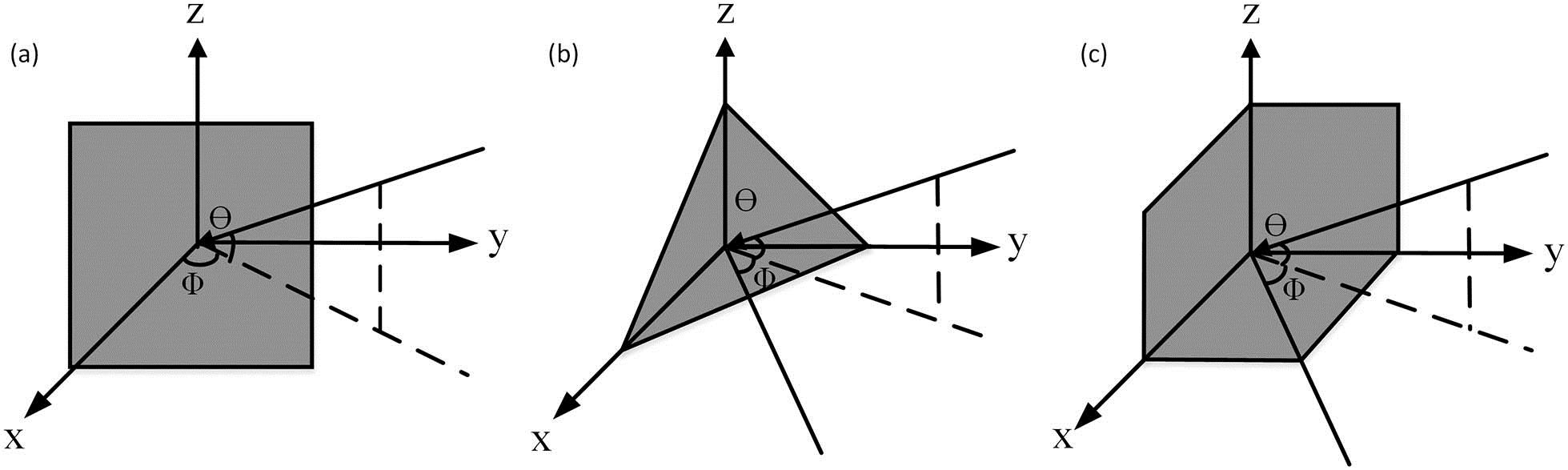
Figure 1 shows the geometry of the metal plates and the different kinds of trihedral corner reflectors[15]. The azimuthal angle is , and the elevation angle is .

Figure 1.(a) Geometry of a metal plate. (b) The geometry of a triangular trihedral corner reflector. (c) The geometry of a square trihedral corner reflector.
For a metal plate, its main scattering procurements include the reflection of its surfaces, diffraction of the edges, and the backscattering from surface traveling wave effects[16]. It is more complex for the trihedral corner reflectors.
As shown in Fig. 1, there are two different kinds of trihedral corner reflectors, including triangular trihedral corner reflectors and square trihedral corner reflectors. The former consists of three right triangular plates, and the latter are made up of three square plates[15].
Figure 2.Schematic diagram of the 0.1 THz compact radar system.
Using the commercially available software CST Studio Suite, which is one of the most reliable softwares in the field of RCS simulation[17], we can calculate the RCS. The ways to predict RCS include geometrical optics (GO), physical optics (PO), geometrical theory of diffraction (GTD), uniform asymptotic theory (UAT), uniform theory of diffraction (UTD), method of moments (MoM), and hybrid method (HM)[10]. Referring to the different methods, different solvers are provided in the CST software. It is important to choose a suitable method, because all thes ways have their own strengths and weakness as well as scope of application[18]. A simple way to choose a solver is by recording the electric size of the targets.
Before simulation, a concept that should be clear is that the electric size means that the geometric dimension is divided by the wavelength. In this Letter, the simulated models are , , and , and the wavelength of the plane wave is 3 mm, so the electric sizes are 3.3, 5, and 6.8, respectively, which belong to electrically small sizes. Among those different algorithms, MoM is designed for that.
So, in this Letter, the solver chosen for generating solutions is the integral equation solver based on the MoM method and in the monostatic scattering mode. The models include plates, triangular trihedral corner reflectors, and square trihedral corner reflectors in different sizes, which are coincident with the targets measured in the experiment.
The 0.1 THz compact radar system, shown in Fig. 2, consists of five major functional components, the Gunn diode, the Schottky diode detector, the optical path, the target, and the data acquisition system[19].
Figure 3.(Color online) Comparison of the experimental results and the numerical simulations for different sizes of metal plates: (a) ; (b) ; (c) .
The Gunn diode generates electromagnetic radiation at 0.1 THz. Then, the Gaussian beam is propagated in a polymethylpentene (TPX) lens behind the source, which is used for collimation[20]. The high resistivity silicon wafer can split the beam into two lights[21]. The transmitted beam can illuminate the target that is located on the rotating platform, while the reflected beam is absorbed by the anechoic materials. Radiation that is back reflected from the target and the high resistivity silicon wafer is collected by the Schottky diode detector. The data acquisition system includes a phase locked amplifier, which can magnify and process the signals, and a computer that can obtain the data for the subsequent treatment. At the same time, the target is located on the rotating platform, which is controlled by the stepping motor controller. The procedure in the computer can control the phase locked amplifier as well as the stepping motor controller and display the measurement results in time.
The models are mounted on a support structure, which is made from Vero White materials that have low reflection. Moreover, there are anechoic materials specifically designed for THz around the experimental table. This is to minimize the amount of radiation scattered back into the receiver by objects other than the targets[22].
In the experimental section, two groups of experiments are accomplished. One group uses the plates, and the other group uses the trihedral corner reflectors when the elevation angle is 0°, and the sizes are different. To demonstrate the system’s ability for obtaining the RCS, experimental results are compared with numerical simulations.
The monostatic RCS of the metal plates are shown in Fig. 3. The plates include , , and . The azimuthal angle is from to 40° with an angular resolution of 1°, and the elevation angle is 0°. It illustrates some key differences and similarities between the experimental results and the numerical simulations.
As it illustrated in Fig. 3, the black line is the result of simulations, and the red line is the experimental results. It can be concluded that the trends of the experimental results and the numerical simulations have a great consistency. Besides, the symmetry is good.
For a certain size of the plates, there is a principal lobe and many side lobes, and when the is within the range of and 10°, the errors between the experimental results and the numerical simulations are minimal. When the is beyond the range and 20°, the errors are maximum. As the is larger, the errors are increasing, however the positions and the numbers of the principal lobes and the side lobes are generally accurate.
From Figs. 3(a), 3(b), and 3(c), we can find that as the size of the plates gets larger, the RCS is larger, and the numbers of the side lobes are increasing, while the errors are reduced.
The monostatic RCS of the trihedral corner reflectors are shown in Figs. 4 and 5, respectively, calculated as a function of azimuthal angle with an angular resolution of 1°. The triangular corner reflectors are measured in different sizes of , , and . The azimuthal angle is from to 50°, and the elevation angle is 0°.
Figure 4.(Color online) Comparison of the experimental results and the numerical simulations for different sizes of triangular trihedral corner reflectors: (a) ; (b) ; (c) .
Figure 5.(Color online) Comparison of the experimental results and the numerical simulations for different sizes of square trihedral corner reflectors: (a) ; (b) ; (c) .
From Figs. 4 and 5, it can be concluded that the changes of the experimental results are in good agreement with the numerical simulations. However, the peak values of the experimental results are smaller than that of the numerical simulations, and the symmetry is not good.
For Fig. 4, the errors of are larger. That is because this model is too small to locate, and it is difficult to make sure that the reflector is radiated by the THz. As the sizes are larger, the errors are smaller.
For Fig. 5, it is almost the same, and the symmetry is not good.
Sign up for Chinese Optics Letters TOC. Get the latest issue of Chinese Optics Letters delivered right to you!Sign up now
As we can see, the RCS of the trihedral corner reflectors include the main scattering region and the side lobes. The main scattering region is a result of the internal reflections among the trihedral corner reflectors, and the side lobes are caused by the direct reflection from the single plates[16].
Comparing the data from Figs. 4 and 5, it is obvious that the RCS of the square trihedral corner reflectors is larger than that of the triangular trihedral corner reflectors. The scattering pattern has ripples in the main scattering region, which is caused by the side lobes from each plate[16]. So, the ripples in the square trihedral corner reflectors are more than that in the triangular trihedral corner reflectors.
For the plates, when the is 0°, the sizes of plates are , , and , the peak RCSs of the numerical simulations of plates are , , and , and the peak RCSs of the , , and triangular trihedral corner reflectors are , , and , and the peak RCSs of the square trihedral corner reflectors are , , and . From the above data, we can conclude that the RCS of the trihedral corner reflectors is larger than that of the plates.
What is more, from Figs. 3, 4, and 5, we can see that when the sizes are , , and , the main scattering regions of the plates are from to 10°, to 7°, and to 4°, while the main scattering regions for the , , and triangular trihedral corner reflectors are to 38°, to 39°, and to 40°. It is almost the same for the square trihedral corner reflectors. In this way, the scattering patterns of the trihedral corner reflectors are wider than that of the plates that can be obtained.
From the above three groups’ data, it can be found that the RCSs of trihedral corner reflectors are larger than that of the plates, and the scattering pattern is wider. This is because of the three times internal reflections among the three plates of the trihedral corner reflectors.
From the errors of the metal plates and trihedral corner reflectors, we can see that the errors of the trihedral corner reflectors are larger. The reason is that the trihedral corner reflectors are assembled by three plates manually, which are not strictly vertical. So, the symmetry of the trihedral corner reflectors is not as good as that of the plates, and the measurement peak RCS of the main scattering region is much lower than that of the numerical simulations. Besides, the errors related to the accuracy of the optical path adjustment in which the targets should be illuminated precisely.
Next, we will take an aircraft scale-model, for example, to study the RCS of the aircraft. The size of the model is . In this part, the azimuthal angle is from 0° to 360° with an angular resolution of 0.1°, and result is shown in Fig. 6.
Figure 6.RCS of an aircraft scaled model by using the 0.1 THz compact radar system.
The Fig. 6 shows great symmetry. There are several scattering peaks, such as 45°, 90°, and 180°, which are caused by the direct reflection of the plates. So the experimental results are in good agreement with the physical characteristics of the scaled model.
In conclusion, we both numerically and experimentally investigate the RCS of the metal plates and trihedral corner reflectors with a 0.1 THz compact radar system. By comparing the numerical and experimental results, it can be deduced that the 0.1 THz compact radar system is practical for the RCS measurement. Then, we investigate the RCS of an aircraft scaled model, and the experimental results are in good agreement with the physical characteristics of the scaled model, which verifies the effectiveness of this system. So, our compact radar system can be used to measure the RCS of the scaled models of the tactics targets, and thus can be beneficial for acquiring the RCS of full-scaled tactic targets in microwave.
References
[1] W. Liu, Y. H. Wang, Z. Yan. Proceedings of 2013 IEEE 11th International Conference on Electronic Measurement & Instruments (ICEMI), 741(2013).
[2] K. Iwaszczuk, H. Heiselberg, P. U. Jepsen. Opt. Express, 18, 26399(2010).
[3] T. M. Goyette, J. C. Dickinson, J. Waldman, W. E. Nixon. Proc. SPIE, 4053, 615(2000).
[4] M. J. Coulombe, T. Horgan, J. Waldman, J. Neilson, S. Carter, W. Nixon. Antenna Measurements & Techniques Association Proceedings(1996).
[5] G. B. Demartinis, M. J. Coulombe, T. M. Horgan, R. H. Giles, W. E. Nixon. Jpn. J. Clinical Med., 28, 3(2010).
[6] Z. Zheng, S. Lu, Y. Li, L. Chen, S. Wen. Chin. Opt. Lett., 10, 100605(2012).
[7] Y. Bai, J. Tang, R. Xu, P. Liu. Chin. Opt. Lett., 14, 093201(2016).
[8] Q. Liang, G. Klatt, N. Kraub, O. Kukharenko, T. Dekorsy. Chin. Opt. Lett., 13, 093001(2015).
[9] Y. Yang. Research on terahertz target scattering characteristics and radar standard target cross section(2013).
[10] Y. H. Peikang, X. Xiaojian. Radar Target Characteristic(2006).
[11] Z. Zhang, X. Wei, C. Liu, K. Wang, J. Liu, Z. Yang. Chin. Opt. Lett., 13, 022201(2015).
[12] K. Sarabandi, C. Tsen-Chieh. IEEE Trans. Antennas Propag., 44, 1348(1996).
[13] K. Sarabandi, T. C. Chiu. Geoscience and Remote Sensing Symposium, 1995. IGARSS ‘95. ‘Quantitative Remote Sensing for Science and Applications’, International, 2241(1995).
[14] W. Xianliang. J. Anhui Univ. Nat. Sci. Ed., 24, 85(2000).
[15] A. C. Polycarpou, C. A. Balanis, P. A. Tirkas. Antennas and Propagation Society International Symposium, 1993. AP-S. Digest, 1428(1993).
[16] Y. Ruan. Radar Cross Section and Stealth Technology(1998).
[17] M. A. Hossain, Z. U. Faysal, M. S. Sobhan, F. O. Ara. International Conference on Electrical Engineering and Information & Communication Technology (ICEEICT), 1(2014).
[18] CST STUDIO SUITE 2014.
[19] X. Nie, F. Xiang, X. Huang, J. Liu, Z. Yang, K. Wang. Laser Technol., 40, 676(2016).
[20] W. Menzel, B. Hunder. Electron. Lett., 20, 768(1984).
[21] T. Li, D. Yang, J. Wang. Chin. Opt. Lett., 12, 082501(2014).
[22] L. Zhang. Measurement and Imaging Diagnosis of Radar Target Scattering Characteristics(2009).