Shanghai Key Lab of Modern Optical System, School of Optical-Electrical and Computing Engineering, University of Shanghai for Science and Technology, Shanghai 200093, China
Xinyue Guo, Xin Li, Ruyi Huang. Adaptive multiple-input multiple-output mode switching for indoor visible light communication system with orthogonal frequency division multiplexing modulation[J]. Chinese Optics Letters, 2017, 15(11): 110604
Copy Citation Text
We propose and experimentally demonstrate an adaptive multiple-input multiple-output (MIMO) mode switching scheme for an indoor visible light communication system combined with orthogonal frequency division multiplexing modulation. Only requiring 1 bit feedback from the receiver, the MIMO mode at the transmitter switches between spatial multiplexing and transmit diversity adapting to the channel correlation. In such a way, we can take advantage of both spatial multiplexing and transmit diversity, where the spatial multiplexing benefits for its multiplexing gain in the low channel correlation environment, and the transmit diversity is robust to high channel correlation. Experimental results validate the performance improvement over the pure spatial multiplexing or transmit diversity system. With the increasing of the channel correlation, the measured bit error rates of the proposed system are below the 7% pre-forward error correction (pre-FEC) limit of when the transmitted data rate is 50 Mb/s, and below the 20% pre-FEC threshold of when the transmitted data rate is raised up to 100 Mb/s.
Visible light communication (VLC) based on white light emitting diodes (LEDs) has recently emerged as a compelling wireless communication technology beyond traditional radio frequency (RF) communications. Compared to traditional RF communications, VLC offers several advantages, including cost effectiveness, licensing free, immunity to electromagnetic interference, and high security[1–3]. However, the modulation bandwidth of LEDs is very limited, where signals modulated at high frequencies are severely attenuated, resulting in serious inter-symbol interference (ISI) for high-speed transmissions[2]. Therefore, it is vital to employ spectral-efficient techniques to achieve high data rate. Among existing works, the orthogonal frequency division multiplexing (OFDM) scheme has been proved particularly useful for the VLC system, because the channel is decomposed into multiple frequency-flat channels, and the ISI can be eliminated[4,5].
Besides, the multiple-input multiple-output (MIMO) technique has also been considered a promising approach to combine with OFDM to further increase the data rate without the additional need of frequency resources[6]. Usually there are multiple LEDs in a room to provide sufficient illumination; as a result, it is natural to implement the MIMO technique to realize parallel data transmission. In VLC, MIMO schemes have already been proved to be able to provide gains even under line-of-sight (LOS) conditions in contrast to the use of MIMO in the RF domain[7]. Spatial multiplexing, as one of the mainstream MIMO schemes, is able to transmit multiple data streams simultaneously on different LEDs with high data rates[6–9]. However, it only enjoys the multiplexing gain when the channel correlation is sufficiently low[7,10]. Once the channel is highly correlated, i.e., channel gains between transmitters and receivers are similar to each other, it would be difficult for the receiver to separate the single data streams.
However, the channel of the typical indoor VLC MIMO environment tends to be highly correlated as Lambertian surfaces of multiple LEDs render similar coefficients among MIMO channels[10]. Several methods have been proposed to attack the high channel correlation problem. For instance, power imbalance is used to reduce the channel correlation by allocating transmission power unequally[7]. However, the transmission power of some channels may be too low to provide a sufficient signal-to-noise ratio (SNR) for decoding. A link-blocked receiver is another way to decrease channel correlation by placing an opaque boundary to block a particular link from an LED to a photodiode (PD)[7]. Such a simple way obviously restricts the receiver moving around the room freely. Imaging MIMO, which creates an approximate image of the source array on a detector array by using lenses, forms an uncorrelated channel matrix[8]. However, precise alignment is crucial to focusing an LED image onto a dedicated detector, which needs extra efforts to calibrate in practice.
Sign up for Chinese Optics Letters TOC. Get the latest issue of Chinese Optics Letters delivered right to you!Sign up now
Different from spatial multiplexing, another MIMO scheme based on transmit diversity has also been applied in VLC, where same information-bearing signals are sent from multiple LEDs simultaneously[11–13]. As a result, transmit diversity benefits for its high reliability and insensitivity to channel correlation, but lack of multiplexing gains[7]. In order to maintain the same data rate as spatial multiplexing, transmit diversity has to adopt high-order modulation, resulting in a smaller Euclidean distance of the transmit constellation and then low performance in low SNR regions.
In this Letter, we propose and experimentally demonstrate a switching MIMO scheme, adapting to VLC MIMO channel correlation between two MIMO modes. When the channel correlation is low, high multiplexing gains can be achieved by spatial multiplexing. Correspondingly, when the channel correlation is high, the transmit diversity is a better choice. In such a way, we can take the advantages of both spatial multiplexing and transmit diversity without needing additional auxiliary methods to reduce the channel correlation. The channel of an indoor VLC system can be easily estimated by conventional training-based approaches, by which the MIMO mode can be decided by the estimated channel at the receiver. The only cost of this scheme is to periodically feedback 1 bit information to the transmitter, indicating which MIMO mode should be used, e.g., bit ‘0’ means choosing spatial multiplexing, and bit ‘1’ indicates choosing transmit diversity. Experimental results confirm the performance improvement of the proposed adaptive MIMO system. With the increasing of the channel correlation, the measured bit error rates (BERs) of the proposed system are always below the 7% pre-forward error correction (pre-FEC) threshold of when the transmitted data rate is 50 Mb/s with a limited bandwidth of 12.5 MHz. When the transmitted data rate is raised up to 100 Mb/s with the same bandwidth, the measured BERs are under the 20% pre-FEC threshold of .
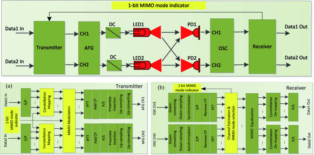
The block diagram of the proposed adaptive MIMO VLC system with OFDM modulation is presented in Fig. 1, where a simple MIMO configuration with two transmitters and two receivers is considered as an example. In the demonstration, the vertical Bell laboratories layered space-time (V-BLAST) architecture[14] and the Alamouti coding[15] are chosen as the mechanisms to realize spatial multiplexing and transmit diversity, respectively, and the direct current (DC)-biased OFDM scheme is used[16]. To keep the data rate fixed, when -ary quadrature amplitude modulation (QAM) is used in the V-BLAST scheme, -ary QAM is required in the Alamouti coding scheme, correspondingly.
Figure 1.Architecture for the proposed adaptive MIMO VLC system, (a) block diagram of transmitter, (b) block diagram of receiver.
At the transmitter, two streams of random binary input data are first converted into parallel sub-streams, where each sub-stream corresponds to a frequency-flat sub-channel in the OFDM system. The MIMO mode indicator, which is fed back from the receiver, decides the MIMO mode and the corresponding constellation size of QAM signals. Constellation mapping and MIMO modulation are implemented for each sub-channel. OFDM modulation is realized by inverse fast Fourier transform (IFFT) and a cyclic prefix (CP) is attached. Then, parallel sub-streams are recovered to serial data streams. Two orthogonal preambles are inserted in front of the data streams separately, which are required for synchronization and channel estimation at the receiver. Finally, data streams are up-sampled and up-converted to a certain carrier, where complex-to-real-value conversion is carried out and real-value OFDM symbols can be obtained[16].
In the experiment, an arbitrary function generator (AFG) is used to generate transmitted signals. DC supplied by AFG is offset to ensure that the transmitted signals are positive. Then, the mixed signals are transmitted through LEDs in the form of optical power. At the receiver, optical signals entering the PDs are converted into electrical signals. Note that crosstalk exists between the channels as light from a single LED falls on multiple PDs. The superimposed signals are recorded by a high-speed digital oscilloscope (OSC) and then sent for demodulation.
Offline demodulation is the inverse process of the modulation at the transmitter. The DC is first removed from the received signals; afterward, down-converting and down-sampling are performed. The starting positions of data streams are detected by synchronization. After CP removal and OFDM demodulation by the fast Fourier transform (FFT), parallel sub-channels are formed again in the frequency domain. A channel is estimated by the preamble, which also provides the channel correlation. Then, the channel mode can be decided with a 1 bit MIMO mode indicator fed back to the transmitter. Channel crosstalk is eliminated by MIMO equalization. Finally, constellation de-mapping is conducted, and two binary data streams are recovered.
We establish the MIMO switching criterion based on the BER, which connects to the minimum Euclidean distance of the constellation at the receiver[17]. The lower bound of the minimum Euclidean distance at the receiver for the V-BLAST scheme is expressed as[18]where is the number of LEDs, is the channel matrix, is the squared minimum Euclidean distance of the transmitted constellation in the V-BLAST scheme, and is the minimum singular value of the channel matrix.
The upper bound of the minimum Euclidean distance at the receiver for the Alamouti coding scheme is denoted as[18]where denotes the squared minimum Euclidean distance of the transmitted constellation in the Alamouti coding scheme, and is the Frobenius norm.
By comparing Eq. (1) with Eq. (2), we find that the V-BLAST scheme is preferred when
Equation (3) suggests that the worst minimum distance of V-BLAST scheme is better than the best minimum distance for the Alamouti coding scheme. In Eq. (3), we take the square root of both sides and find that the V-BLAST scheme is preferred if where , and is known as the Demmel condition number[19]. Like the regular condition number, the Demmel condition number measures how singular the channel matrix is. That is, the less spread out the singular values are, the larger the multiplexing gains that can be achieved. Therefore, the Demmel condition number reflects the correlation of the MIMO channel. Since and are determined as soon as the data rate is given, the selection of V-BLAST or Alamouti coding scheme only depends on the channel correlation.
The experimental setup is shown in Fig. 2. Signals are generated by an AFG (Tektronix AFG3252C), and received by a high-speed digital OSC (Tektronix MSO4104). The signal peak-to-peak voltage is set to 3 V with 2.5 V DC offset. We use two off-the-shelf red LEDs (Cree XLamp XP-E) as the transmitters with center wavelengths of 620 nm. We use two PD modules (Hamamatsu C12702-11, 0.42A/W responsivity at 620 nm) with active area and about 100 MHz bandwidth as receivers.
Figure 2.Experimental setup of the proposed adaptive MIMO VLC system.
The system parameters of our experiments are listed in Table 1. The measured amplitude frequency responses of two different VLC MIMO channels are presented in Fig. 3, where (, 2; , 2) represents the channel gain in the frequency domain from the th LED to the th PD. The channel gain consists of the responses of the LED, optical channel, and the PD, which is estimated by the least square (LS) algorithm in the frequency domain at the receiver. As shown in Fig. 3, the measured channel frequency response is strongly attenuated at high frequencies. Because the optical channel gains depend on the relative positions of the transmitters and receivers, different channel gains in Figs. 3(a) and 3(b) indicate two different placements of the transmitters and receivers.
Since the channel estimation and the MIMO equalization are both performed in the frequency domain, the channel correlation is also evaluated in the frequency domain. As a result, the Demmel condition number is calculated based on the frequency-domain estimated channel. Considering that the channel is divided into sub-channels in the OFDM system, each sub-channel would correspond to a Demmel condition number. In Fig. 4, experimental results of the Demmel condition number for the two channel cases in Fig. 3 are presented. As shown, the Demmel condition numbers vary among sub-channels, especially dramatically at high frequencies. That is because the random noise has more relative influence on small values of channel gains at the high frequency region. Comparing the values of the Demmel condition number between two channels, the correlation of the second channel is higher than the first one. This result is reasonable since the channel gains of the second channel are more similar to each other.
Figure 4.Demmel condition numbers of sub-channels. (a) Channel 1 and (b) Channel 2.
As mentioned above, the Demmel condition numbers at the low frequency region are considered more accurate. Therefore, it is more reliable to choose the MIMO mode by only employing the Demmel condition numbers on low frequency sub-channels. Based on the idea, the average Demmel condition number is calculated by averaging the Demmel condition numbers on the first half-part of the sub-channels. Then, the average Demmel condition number is compared with the switching threshold to decide the proper MIMO mode for all sub-channels. Take Channel 1 in Fig. 3(a) as an example, when the data rate is equal to 50 Mb/s, 4-QAM modulation is required in the V-BLAST scheme and 16-QAM is used in the Alamouti coding scheme. By averaging the Demmel condition numbers on the first half-part of the sub-channels, the average Demmel condition number is equal to 2.088. Following the MIMO switching criterion, the switching threshold can be calculated according to Eq. (4), where the V-BLAST scheme is preferred when the Demmel condition number is less than 2.236. So, the V-BLAST scheme is decided. When the data rate is increased up to 100 Mb/s, higher modulation orders are required, where 16-QAM is adopted in the V-BLAST scheme and 256-QAM is used in the Alamouti coding scheme. Since the modulation order in the Alamouti coding scheme grows much faster than the one in the V-BLAST scheme, the BER performance of the Almouti coding scheme would be worse due to its large signal constellation size. Consequently, the switching threshold is also raised up to 4.123. In this case, the V-BLAST scheme is still chosen as the better choice.
To validate the performance improvement, the BER performance of our adaptive MIMO scheme is compared with the pure V-BLAST scheme and the pure Alamouti coding scheme. In the experiments, the transmitted data rates are set as 50 and 100 Mb/s, respectively, with a limited bandwidth of 12.5 MHz. The detailed BER performance of different MIMO schemes is depicted in Figs. 5 and 6. In the figures, three curves denote the BER performance of different MIMO schemes versus the average Demmel condition number, which is calculated by averaging the Demmel condition numbers on the first half-part of the sub-channels.
Figure 5.(Color online) BER versus the average Demmel condition number for 50 Mb/s data rate case.
As shown, with the increasing of the channel correlation, only the BER of the adaptive MIMO scheme can always be kept below the 7% pre-FEC threshold of for 50 Mb/s data rate case, which confirms the effectiveness of the proposed switching criterion. When the channel correlation is low, the BER of the V-BLAST is lower than Almouti coding. This is because the Almouti coding scheme has to use a larger signal constellation size to keep the transmit data rate constant, resulting in worse BER performance. However, when the channel correlation increases, the Alamouti coding scheme performs better. This implies that V-BLAST suffers from performance loss with high channel correlation, while the BER changes little in the Alamouti coding scheme. Even though a larger signal constellation size has to be used, the Alamouti coding scheme still gains a better performance for its robustness to the channel correlation. The higher the channel correlation is, the larger the BER gap between V-BLAST and the Alamouti coding scheme would be. It is worth noting that the MIMO mode can switch to the better one based on the proposed criterion in most cases of channel correlation; however, the wrong switching may also exist, as outlined by the rectangle shown in Fig. 5. Since the switching criterion is based on the BER bounds, it is possible that the exact BER of the V-BLAST is lower than the Alamouti coding, even though the lower bound of the minimum Euclidean distance for V-BLAST is lower than the upper bound for the Alamouti coding. Obviously, this tends to happen when the Demmel condition number is around the threshold.
When the data rate is raised up to 100 Mb/s, similar results can be achieved as in the 50 Mb/s case, where BERs of the adaptive MIMO scheme are kept under the 20% pre-FEC limit of . Experimental results validate the performance improvement over pure V-BLAST or Alamouti coding system. Besides, experimental results also prove that the switching threshold is increased with the data rate growing.
Moreover, the BER performance is also evaluated in terms of the distance between the LED plane and the PD plane, the distance between LEDs, and the distance between PDs, which are denoted as , , and , respectively. In the experiments, LEDs and PDs are placed symmetrically; meanwhile, the LED plane and the PD plane are parallel, as shown in Fig. 2. The transmitted data rate is set as 50 Mb/s. Figures 7, 8, and 9 present the experimental results of the BER performance versus , , and , respectively. With increasing, the channel correlation is also increased. The reason is that differences among distances between the th LED and th PD would become smaller when is increased, leading to more similar link gains of the channel matrix. Similar results can be achieved when the or is decreased. As a result, the MIMO mode is adaptively switched to the Alamouti coding scheme when the V-BLAST performs worse, as shown in Figs. 7, 8, and 9.
Figure 7.(Color online) BER versus distance between LED plane and the PD plane.
In conclusion, we propose and demonstrate an adaptive switching MIMO scheme combined with OFDM modulation for an indoor VLC system. The average Demmel condition number is calculated at the receiver as the indicator of channel correlation, which is feedback to the transmitter to decide the better MIMO modes between spatial multiplexing and transmit diversity. Then, in the experimental demonstration, the well-known V-BLAST and Alamouti coding scheme are chosen as the mechanisms to realize spatial multiplexing and transmit diversity. Experimental results show that the adaptive system can switch to the MIMO mode with a lower BER in most cases. In such a way, the performance of the adaptive MIMO scheme can be significantly improved compared with the pure V-BLAST or Alamouti coding scheme. Future work includes combining the power and rate optimization with the adaptive MIMO scheme to further increase the data rates.
[14] P. W. Wolniansky, G. J. Foschini, G. D. Golden, R. A. Valenzuela. Proceedings of International Symposium on Signals, Systems, and Electronics, 295(1998).
Xinyue Guo, Xin Li, Ruyi Huang. Adaptive multiple-input multiple-output mode switching for indoor visible light communication system with orthogonal frequency division multiplexing modulation[J]. Chinese Optics Letters, 2017, 15(11): 110604