Abstract
All-fiber few-mode erbium-doped fiber amplifiers (FM-EDFAs) with isolation and wavelength division multiplexers (IWDMs) have been developed to enable flexible pumping in different directions. The FM-EDFA can achieve >30 dB modal gain with <0.3 dB differential modal gain (DMG). We experimentally simulate the DMG performance of a cascade FM-EDFA system using the equivalent spectrum method. The overall DMG reaches 1.84 dB after 10-stage amplification. We also build a recirculating loop to simulate the system, and the developed FM-EDFA can support transmission up to 3270 km within a 2 dB overall DMG by optimizing the few-mode fiber length in the loop.
1. Introduction
In order to meet the increasing demand for transmission capacity and break through the nonlinear Shannon limit, in recent years the spatial dimension has been used to further expand the transmission capacity[1,2]. As one of many space division multiplexing (SDM) technologies, mode division multiplexing (MDM) has been extensively and deeply studied[3,4]. In long-haul MDM transmission systems, few-mode erbium-doped fiber amplifiers (FM-EDFAs) are necessary to save costs and energy consumption[5]. However, an excessive differential mode gain (DMG) for FM-EDFAs will lead to the outage of communication systems. The DMG depends on the overlap between the intensity profiles of the signal and the pump modes and the erbium-ion doping distribution. Thus, there are usually three techniques used to reduce the DMG by changing the refractive index distribution, optimizing the pump configuration, and designing the doping distribution of the erbium ions[4].
Initially, FM-EDFAs were realized by the free-space coupling devices, with high-precision alignment and large-volume requirements. The fiberization of FM-EDFAs is desirable for commercialization and practical application. Mode-selective photonic lanterns (MSPLs) are often used in FM-EDFAs for multiplexing the signal and the pump light, but they cannot filter out the pump at the output[6]. Few-mode wavelength division multiplexers (FM-WDMs), as wavelength (de-)multiplexers of few-mode signals and pumps, have been produced to build up all-fiber FM-EDFAs with a DMG of more than 1.6 dB[7–9]. Certainly, the fiberization of FM-EDFAs can also be achieved by cladding pumping[10,11], in spite of high pump power or low pump usage. Recently, Xu et al.[12] presented a high-gain integrated in-line three-mode EDFA, enabling 3840-km long-haul transmission, in which two sections of few-mode erbium-doped fibers (FM-EDFs) are used by forward and backward pumping ways, respectively. Currently, all-fiber FM-EDFAs with high gain () and low DMG () have been achieved in experiments supporting only , , and three-mode signals.
In long-haul MDM transmission systems, the recirculating loop schemes can also be applied by means of mode multiplexers and demultiplexers, and the length of the few-mode fibers (FMFs) used in the loops is usually less than 65 km[12–16]. In order to get rid of the complicated and expensive loop configuration, in the paper, we use the equivalent spectrum method[17] to experimentally simulate the DMG performance of the cascade FM-EDFA system, in which the process of multi-stage amplification is replaced by multiple measurements on the FM-EDFA. First, we fabricate a kind of new device, namely, optical isolation and wavelength division multiplexers (IWDMs), to build up all-fiber FM-EDFAs capable of flexibly supporting forward, backward, and bi-directional pumping. A section of 3 m-long three-layer ion-doped double-cladding EDF supporting , , , and signal modes[11] is utilized for the high gain of about 32 dB, with the DMG of 0.27 dB, by a single forward-pumped mode at 1480 nm. Then, we use the equivalent spectrum method to experimentally simulate the DMG performance of the cascade four-mode (4M) EDFA system, and the overall DMG after 10-stage amplification is up to 1.84 dB. Finally, a recirculating loop model with the 4M-EDFA is built up by the VPI software, and the simulation results are basically consistent with the experimental data. By optimizing the length of the few-mode transmission fiber in the recirculating loop, our simulation shows that the cascade 4M-EDFA system can achieve the transmission distance of 3270 km within the overall DMG of 2 dB.
Sign up for Chinese Optics Letters TOC. Get the latest issue of Chinese Optics Letters delivered right to you!Sign up now
2. Setup of IWDM-Based FM-EDFAs
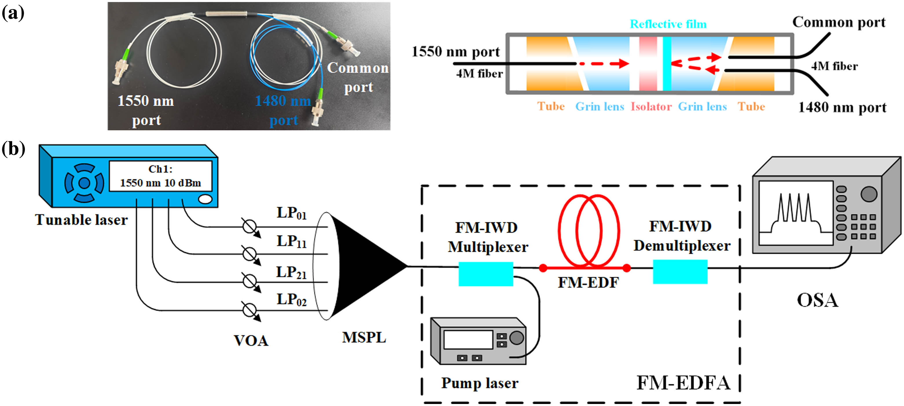
Compared with the traditional single-mode EDFAs, the active optical fibers and coupling devices used in FM-EDFAs need the support of the transmission of few-mode signals and pumps, and the resulting FM-EDFAs are also required for modal gain equalization, i.e., as low a DMG as possible. Here, we construct an all-fiber FM-EDFA, as shown in Fig. 1. Compared with the previous works, we use the optical integrated devices with optical isolation and wavelength division (IWD) multiplexing to develop all-fiber FM-EDFAs. The FM-EDFAs are capable of supporting the simultaneous amplification of , , , and modes in the forward, backward, or bi-directional pumping ways.

Figure 1.All-fiber FM-EDFA based on IWDMs. (a) FM-IWDM. (b) All-fiber FM-EDFA configuration.
Figure 1(a) shows the FM-IWDM and its structure. For the FM-IWDM, the signal light is input to the 1550 nm port, then passes through the self-focusing lens, the forward isolator, and the reflective film in turn, and lastly arrives at the output end of the FM-IWDM, along with the 1480 nm pump reflected by the reflective film. The forward isolator is used to suppress the reflection of the signal and pump modes. The FM-IWD demultiplexer is similar to the multiplexer in structure, except for the isolation direction. Here, the pigtails connected to three ports of the IWDMs are four-mode fibers and can bear the laser power of up to 3 W by beam expansion. Table 1 lists the insertion loss and isolation performance of the FM-IWD multiplexer and demultiplexer. From Table 1, for the 1550 nm signal light, the FM-IWDMs have the isolation of more than 40 dB, and the insertion loss of the demultiplexer is about 1.6 dB, slightly greater than that of the multiplexer by 0.5 dB or more, while the insertion loss of the FM-IWDMs at the 1480 nm pump is less than 1 dB, and the isolation is greater than 50 dB.
| | IWD Multiplexer | IWD Demultiplexer |
|---|
| Mode | LP01 | LP11 | LP21 | LP02 | LP01 | LP11 | LP21 | LP02 |
|---|
| 1550 nm insertion loss/dB | 0.79 | 0.97 | 0.89 | 0.87 | 1.58 | 1.55 | 1.51 | 1.66 |
| 1550 nm isolation/dB | 48.79 | 47.63 | 44.87 | 47.72 | 42.45 | 44.54 | 43.48 | 46.08 |
| 1480 nm insertion loss/dB | 0.54 | 0.84 | 0.52 | 0.42 | 0.28 | 0.79 | 0.78 | 0.88 |
| 1480 nm isolation/dB | ≥ 50 | ≥ 50 |
Table 1. Test Data for the FM-IWDMs
The all-fiber FM-EDFA is mainly composed of two IWDMs and a section of FM-EDF by the forward, backward, or bidirectional pumping way, as shown in Fig. 1(a). Four continuous waves (CWs) output from the tunable laser are mode-converted into , , , and modes through the MSPL and then injected into the IWDM as the input MDM signals. The modal optical powers input to the FM-EDFA can be adjusted by the variable optical attenuators (VOAs). Forward -mode pumping is applied by directly connecting the pump laser with the 1480 nm port of the IWDM. A section of a 3-m-long triple-layer erbium-ion-doped double-cladding FM-EDF with a central refractive index (RI) depression is used to balance the intensity distribution of the lower and higher-order modes for the lower DMG[11]. This refractive index profile can also reduce mode coupling and ensure high isolation between modes.
In MDM transmission systems, mode crosstalk is very important for multi-input multi-output (MIMO) signal processing. As shown in Fig. 1, the mode crosstalk may be introduced by MSPL, IWDM, FM-EDF bending, or fiber coupling. According to our measurements, the IWDMs can well preserve the purity and fidelity of each signal mode. Thus, the mode crosstalk mainly comes from the MSPL and FM-EDF bending. The influence of mode crosstalk on the modal gain can be removed by using the wavelength mapping method[9].
Next, the modal gain is measured by the wavelength mapping method using the optical spectrum analyzer (OSA, Yokogawa AQ6375). Figure 2(a) shows the input optical spectrum of four signal modes, corresponding to 1549.15 nm, 1549.25 nm, 1549.35 nm, and 1549.45 nm, respectively. The 3-m-long FM-EDF is used in our experiment, and the signal power input to the IWDM is for each mode. The variations of the modal gain and the DMG with the forward -mode pump power are shown in Fig. 2(b). It can be seen from Fig. 2(b) that, with the increase of the pump power, the modal gains gradually increase to saturation, but the DMG gradually decreases, which is similar to the cladding pumping case[11]. When the pump power is the maximum of 940 mW, the output spectrum is shown in Fig. 2(c), and the modal gains are, respectively, 31.79 dB, 31.94 dB, 32.06 dB, and 31.95 dB for , , , and modes, with a minimum DMG of 0.27 dB. Compared with the cladding pumping, the core pumping scheme has a higher pump efficiency (lower pump power), higher modal gain, and smaller DMG.
Figure 2.Experimental results for the IWDM-based FM-EDFA. (a) The input signal spectrum, (b) the variations of the modal gain and the DMG with the forward LP01-mode pump power, and (c) the output spectrum at the pump power of 940 mW.
The noise figures (NFs) are calculated from , where and are, respectively, the modal gain and output amplified spontaneous emission (ASE) noise power density; is Planck’s constant; is the signal frequency; and the ASE noise bandwidth . Clearly, depends on the modal gain and the noise power . At the maximum pump power of 940 mW, the modal NFs are 10.80 dB, 10.66 dB, 10.54 dB, and 10.65 dB, respectively. In our calculation, is approximately taken as the average value of the total ASE power densities at 1549.05 nm and 1549.6 nm for all signal modes. In addition, the non-optimal fiber coupling between the graded index IWDM pigtail and the double-clad FM-EDF will lead to an excess loss and then raise the NFs due to a relative reduction of signal gain[18]. It should be pointed out that a 1480 nm pump has a higher quantum efficiency than a 980 nm pump, but the latter is usually used to obtain lower NFs in the same pumping way[19]. In principle, IWDMs can also be fabricated for 980 nm pumps by changing the reflective film, and the resulting FM-EDFA will support more pump modes.
3. DMG Performance of the Cascade FM-EDFA System
In this section, we apply the FM-EDFA to the long-haul MDM transmission system, as shown in Fig. 3. The few-mode signals output from the MDM transmitter (Tx) first pass through a section of the FMF with the length of and then are amplified by the FM-EDFAs followed by the FMFs with the length of () to compensate for the transmission fiber loss. The last segment of FMF () is linked with the MDM receiver (Rx). The lengths and can be determined by the required optical powers input to the first-stage FM-EDFA and the MDM receiver, respectively. In the cascade FM-EDFA transmission system, each stage of the FM-EDFA will introduce ASE noise and will also bring about the DMG.
Figure 3.Cascade FM-EDFA system for long-haul transmission of MDM signals.
Here, we adopt the equivalent spectrum method to measure the DMG performance of the cascade FM-EDFA system. The experimental setup for the equivalent spectrum method is mainly composed of three parts: the optical spectrum generator, the FM-EDFA under test, and the OSA, as shown in Fig. 4. In the optical spectrum generator, the 0.8 nm band-limiting ASE noise is generated by the ASE noise laser and 100 GHz dense wavelength division multiplexing (DWDM), and then coupled to the mode port of the MSPL along with the input signals. The powers of the input MDM signals and the ASE noise are controlled by the VOAs to obtain the required spectrum. The input spectrum of the FM-EDFA is reconstructed by the spectrum generator, and the corresponding signal and ASE noise powers are equal to those output from the preceding FM-EDFA stage minus the fiber attenuation. In turn, the overall DMG performance for the cascade FM-EDFA system can be achieved by the stage-by-stage test. As for each stage, the power spectral density of the ASE noise is approximately equal for all signal modes. The equivalent spectrum method not only may avoid the expensive and complex recirculating loop configuration but also may be easier to implement.
Figure 4.Experimental test setup for the equivalent spectrum method.
As shown in Fig. 2, the FM-EDFA under test is still built up by means of a 940 mW -mode pump. The optical power of each mode input to the first-stage FM-EDFA is , in the absence of ASE noise. In this case, the amplified modal powers are, respectively, 11.78 dBm, 11.79 dBm, 11.99 dBm, and 11.7 dBm, with a DMG of 0.29 dB. The output ASE noise power density is . Clearly, the modal gain for the first-stage FM-EDFA is about 32 dB. Here, we set the transmission fiber loss as 32 dB and neglect the mode-dependent loss (MDL) for simplicity[20,21]. In practice, the MDL is easily considered as well to minimize the overall DMG of the transmission system.
Then, we take a test on the second-stage FM-EDFA. Considering the optical attenuation of the FMF after the 1st-stage FM-EDFA, the modal powers input to the second-stage FM-EDFA should be, respectively, , , , and , with an average noise power of . The required MDM signals are obtained from the optical spectrum generator. The other amplification stages are carried out in the same way. Figure 5(a) shows the amplified powers and overall DMG output from the FM-EDFA stages. From Fig. 5(a), as the number of stages increases, the amplified power of the mode basically remains unchanged, while the amplified powers of other modes decrease. This difference may be explained by the fact that the modal power out from the FM-EDFAs depends positively on the input signal power. For the first-stage FM-EDFA, the output powers of , , , and modes are 11.79 dBm, 11.94 dBm, 12.06 dBm, and 11.95 dBm, respectively. After passing through the following FMF of 32 dB attenuation, the -mode power input to the second FM-EDFA is basically unchanged and always larger than those of the other three signal modes. The overall DMG gradually increases with the stage number and ultimately arrives at 1.84 dB after the 10th-stage FM-EDFA. The corresponding received optical powers for the four modes are , , , and , respectively.
Figure 5.Performance for the cascade FM-EDFA system. (a) Amplified powers and the overall DMG. (b) Output OSNRs and ASE noise power.
According to the optical spectra output from the FM-EDFAs, we can also measure the output OSNR of each mode and ASE noise power dependent on the stage number, as shown in Fig. 5(b). From Fig. 5(b), the OSNRs gradually decrease and the ASE noise power increases with the stage number. For the 10-stage cascade FM-EDFA system, the -mode signal has the lowest OSNR of 21 dB, more than the 100 Gb/s DP-QPSK OSNR threshold of 12.7 dB for error-free transmission after forward error correction (15% SD-FEC). The increasing trend of the ASE noise power gradually flattens out, and the increase amplitude is less than 0.1 dBm/nm per stage when the stage number is greater than eight. According to the degradation trend of the DMG and the ASE noise with the stage number, the noise is still larger than the OSNR threshold when the stage number reaches 20 and the DMG exceeds 3 dB.
4. Simulation and Optimization of Cascade FM-EDFA Systems
In what follows, we build up the simulation model of the IWDM-based FM-EDFA and then construct the recirculating loop for the cascade FM-EDFA system by using the VPI software, as shown in Fig. 6(a). In the layout, the IWDMs are realized by “mode converter + single-mode VOA + mode converter.” The MDM signals are generated from four CW lasers followed by a mode converter. The recirculating counts can be controlled by configuring the loop switch. In the MDM receiver, the few-mode signals are demultiplexed by the mode converter. In our simulation, the configuration parameters, such as the insertion loss of the IWDMs input modal powers, the FMF attenuation, the -mode pump power, the FM-EDF’s length, and the refractive index distribution, are identical to those used in the above experiment. The mode crosstalk and MDL are neglected. In addition, the EDF’s absorption and emission cross sections are taken as follows: and for the 1550 nm signal, and and for the 1480 nm pump. The attenuation of the FMF in the recirculating loop is fixed at 32 dB for each signal mode, equivalent to the fiber length of () for the attenuation coefficient . Figure 6(b) shows the variation of experimental and simulated amplified power with the number of stages, and the simulation results are basically consistent with the experimental data.
Figure 6.Simulation on cascade FM-EDFA systems. (a) Recirculating loop model. (b) Comparison of the simulation and experimental results.
In the following, for the 10-stage cascade FM-EDFA system, we take the FMF length as an optimal variable to simulate the modal powers and the overall DMG received by the MDM receiver. The simulation results are shown in Fig. 7(a). It is clear from Fig. 7(a) that (i) the received optical powers reduce with the increase of and are less than when , and (ii) in the range of , the overall DMG is less than 2 dB, and the minimum DMG of 1.22 dB occurs in the vicinity of . The lower overall DMG means more amplification stages can be added to the cascade transmission system to reach a given DMG limit.
Figure 7.Optimization of the FMF length in the recirculating loop. (a) The system output powers and overall DMG for 10-stage FM-EDFA system. (b) The max stage number of the overall DMG permitted in the limit of 2 dB.
In the limit of 2 dB overall DMG, Fig. 7(b) gives the maximum stage number dependent on the FMF length . The corresponding total transmission distance is still calculated from . From Fig. 7(b), the total transmission distance can reach the maximum of 3270 km () after 20-stage amplification. In this case, the received optical powers of the four modes are , , , and , respectively. In summary, it is very important to optimize the FMF length for the long-haul MDM system composed of the identical FM-EDFAs, and the IWDM-based FM-EDFA developed here is helpful for the realization of low overall DMG.
In the end, according to the simulation model of the IWDM-based FM-EDFA, we also give the dependencies of modal gain on the signal wavelength in the C-band, as shown in Fig. 8. The simulation parameters are identical to those in Fig. 6. From Fig. 8, modal gains slightly decrease with the wavelength increase, with a gain flatness of less than 0.3 dB. Meanwhile, the FM-EDFA also performs a good gain equalization over the whole C-band.
Figure 8.Curves of the modal gain and the DMG in the C-band.
5. Conclusion
We have developed the FM-IWD multiplexer and demultiplexer to build up the all-fiber FM-EDFA supporting , , , and modes. Under the -mode forward pumping, the modal gain is up to about 32 dB, with a DMG of 0.27 dB. On the basis of this, the DMG performance of the cascade FM-EDFA system is experimentally measured by the equivalent spectrum method, and the overall DMG through 10-stage amplification is 1.84 dB for the case of 32 dB fiber attenuation. The recirculating loop model with the IWDM-based FM-EDFA is established by using the VPI software, and the simulation results are basically identical to the experimental data. It is shown by simulation that the IWDM-based FM-EDFA developed here may be applied to the build up 3270-km-long MDM transmission systems with an overall DMG of 2 dB.
References
[1] P. J. Winzer. Making spatial multiplexing a reality. Nat. Photonics, 8, 345(2014).
[2] D. J. Richardson, J. M. Fini, L. E. Nelson. Space-division multiplexing in optical fibres. Nat. Photonics, 7, 354(2013).
[3] H. Liu, H. Wen, G. Li. Applications of weakly-coupled few-mode fibers. Chin. Opt. Lett., 18, 040601(2020).
[4] J. Du, W. Shen, J. Liu et al. Mode division multiplexing: from photonic integration to optical fiber transmission. Chin. Opt. Lett., 19, 091301(2021).
[5] A. E. Willner. Optical Fiber Telecommunications(2020).
[6] G. Lopez-Galmiche, Z. S. Eznaveh, J. E. Antonio-Lopez et al. Few-mode erbium-doped fiber amplifier with photonic lantern for pump spatial mode control. Opt. Lett., 41, 2588(2016).
[7] Z. Zhang, C. Guo, L. Cui et al. All-fiber few-mode erbium-doped fiber amplifier supporting six spatial modes. Chin. Opt. Lett., 17, 100604(2019).
[8] J. Zhu, Y. Yang, Z. Zhang et al. Weakly-coupled MDM-WDM amplification and transmission based on compact FM-EDFA. J. Lightwave Technol., 38, 5163(2020).
[9] Z. Li, L. Pei, J. Zheng et al. Amplification and transmission system with matching multi-layer ion-doped FM-EDFA. J. Lightwave Technol., 41, 695(2022).
[10] Q. Qiu, Z. Gu, L. He et al. High power-efficiency low DMG cladding-pumped few-mode Er/Yb/P co-doped fiber amplifier for mode division multiplexing. J. Lightwave Technol., 40, 7421(2022).
[11] Y. Chang, L. Pei, J. Zheng et al. Demonstration of an all-fiber cladding-pumped FM-EDFA with low differential modal gain. Opt. Laser Technol., 155, 108446(2022).
[12] T. Xu, T. Gao, Y. Wang et al. High-gain integrated in-line few-mode amplifier enabling 3840-km long-haul transmission. Photonics Res., 10, 2794(2022).
[13] V. A. J. M. Sleiffer, Y. Jung, M. Kuschnerov et al. Optical chopper-based re-circulating loop for few-mode fiber transmission. Opt. Lett., 39, 1181(2014).
[14] E. Ip, M. J. Li, K. Bennett et al. 146λ × 6× 19-Gbaud wavelength-and mode-division multiplexed transmission over 10× 50-km spans of few-mode fiber with a gain-equalized few-mode EDFA. J. Lightwave Technol., 32, 790(2013).
[15] R. Ryf, N. K. Fontaine, H. Chen et al. 72-Tb/s transmission over 179-km all-fiber 6-mode span with two cladding pumped in-line amplifiers. European Conference on Optical Communication(2015).
[16] R. Ryf, H. Chen, N. K. Fontaine et al. 10-mode mode-multiplexed transmission with inline amplification. European Conference on Optical Communication(2016).
[17] X. Jiang, B. Wu. Experimental evaluation on OSNR and DMG performance of cascade FM-EDFA systems by equivalent input spectrum method. Opt. Laser Technol., 166, 109628(2023).
[18] M. Salsi, J. Vuong, C. Koebele et al. In-line few-mode optical amplifier with erbium profile tuned to support LP01, LP11, and LP21 mode groups. European Conference on Optical Communication(2012).
[19] P. M. Becker, A. A. Olsson, J. R. Simpson. Erbium-Doped Fiber Amplifiers: Fundamentals and Technology(1999).
[20] H. Tan, J. Zhang, J. Liu et al. Low-loss ring-core fiber supporting 4 mode groups. Conference on Lasers and Electro-Optics(2019).
[21] M. Zuo, D. Ge, J. Liu et al. Long-haul intermodal-MIMO-free MDM transmission based on a weakly coupled multiple-ring-core few-mode fiber. Opt. Express, 30, 5868(2022).