
Qungang Ma, Liangcai Cao, Zehao He, Shengdong Zhang, "Progress of three-dimensional light-field display [Invited]," Chin. Opt. Lett. 17, 111001 (2019)
- Chinese Optics Letters
- Vol. 17, Issue 11, 111001 (2019)
Abstract
1. INTRODUCTION OF THREE-DIMENSIONAL DISPLAY
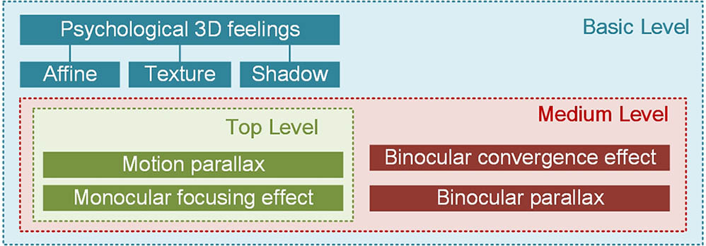
Information in the real world could be acquired by humans through a variety of ways. Among them, more than 70% of information is obtained by visual perception. Through visual information, humans could perceive the three-dimensional (3D) layout of objects in the real world. Human perception of the 3D information could be achieved through pseudo 3D effects, binocular parallax, motion parallax, monocular focus effect, and binocular convergence effect. Pseudo 3D effects, such as affine, texture, and shadow, contain no binocular depth information about the displayed object. They could only deceive the human brain to produce psychological 3D feelings. Binocular parallax refers to the difference between two images for the left and the right eyes, respectively. These two slightly different images are fused by the brain, and then 3D immersion could be obtained. Motion parallax is the movement amounts of objects at different depths that are not equal when a person observes a 3D scene while moving. The monocular focusing effect indicates the adjustment of the lens in human eye for a clearer viewing effect of objects at different depths. The binocular convergence effect means the rotation of the optical axes of two eyes. The intersection of the optical axes will converge at the center of the target object at a specific depth.
Nowadays, humans often observe the real world through display devices instead of on-the-spot observation in most cases. The development status of display devices determines the comprehensiveness and authenticity of humans’ cognition about the real world. According to the richness of the provided indicators, display devices could be divided into three levels, as shown in Fig.
![]()
Figure 1.Three levels of 3D display based on the comprehensiveness and authenticity.
Volumetric 3D display, holographic display, and light-field display are on the top level of 3D display because they could provide vivid 3D display effects similar to the real world. The comparison of them is shown in Table
Sign up for Chinese Optics Letters TOC. Get the latest issue of Chinese Optics Letters delivered right to you!Sign up now
| System Complexity | Data Amount | Calculation Power | Transmission Rate | 3D Effect | |
|---|---|---|---|---|---|
| Volumetric 3D | High | High | High | High | Medium |
| Holography | Low | High | High | High | High |
| Light-field | Low | Medium | Medium | Medium | High |
Table 1. Comparison of Volumetric 3D Display, Holographic Display, and Light-Field Display
2. PRINCIPLE OF LIGHT-FIELD DISPLAY
A. Theoretical Basis of Light-Field Display
The reason why 3D objects can be seen is that the light emitted or reflected by the object is received by human eyes. For specific 3D objects, different images could be seen by the human eyes from different perspectives. This relationship can be quantitatively expressed as
However, it is extremely difficult to process and transmit seven-dimensional functions in real time under the current calculation capacity. Assuming that the intensity of light does not attenuate, and the wavelength does not change during propagation, the seven-dimensional plenoptic function can be simplified to a four-dimensional function, which could be expressed as
In order to realize the reconstruction of the four-dimensional function, special display devices need to be built. The intensity and the direction of the light emitted by each point on the display devices could be accurately controlled. The 3D objects to be displayed can be reconstructed by the display devices indirectly. According to the different ways to realize four-dimensional function, the light-field display could be divided into four categories: they are the layer-based method[
B. Layer-Based Light-Field Display
The schematic of the layer-based light-field display is shown in Fig.
![]()
Figure 2.Schematic diagram of the layer-based light-field display.
The layer-based light-field display employs pixels on multiple planes to render the positions and intensities of points of 3D objects. The depth of field can be improved by increasing the number of layers. The depth of field of the layer-based light-field display exceeds the traditional multi-view stereo display. However, in practical applications, the screen size of each plane is finite, and the effective size of the plane limits the viewing angle of the light-field display.
With the development of the display devices, a new type of layer-based light-field display has appeared, which is called the vector-fields light-field display. The schematic of the vector-fields light-field display is shown in Fig.
![]()
Figure 3.Schematic diagram of vector-fields light-field display.
The advantages of vector-fields light-field display include large viewing angle, high resolution, and high contrast. However, the pixel size of the directional backlight should be as small as possible. Meanwhile, the divergence angle of the exit light rays in the directional backlight panel should be narrow enough. Thus, this technology has high requirements for the design and fabrication of optical waveguides.
C. Projector-Based Light-Field Display
The projector-based light-field display could be divided into two categories: time-division method (TDM) and projector-array method. There are two typical configurations for the TDM light-field display. The first type is shown in Fig.
![]()
Figure 4.Schematic diagram of TDM light-field display[
The advantages of the TDM light-field display include a high resolution and a large viewing angle. However, it has a demanding requirement on the refresh rate of the display devices. The digital micro-mirror device (DMD), which could project 104 images per second, is the most used device in TDM light-field display. Besides, there are mechanical moving parts in the TDM light-field display, which affect the stability of the display system.
The schematic of the projector-array light-field display is shown in Fig.
![]()
Figure 5.Schematic diagram of projector-array light-field display.
Generally, horizontal parallax is more important than vertical parallax in 3D display. Ignoring vertical parallax would greatly reduce the data amount needed by the 3D display system. Besides, the use of projectors with high resolution would make the projector-array light-field display more suitable for the display of large-scale and high-resolution 3D scenes. However, the lack of the vertical parallax limits the quality of the 3D display. Meanwhile, when the number of narrowband sub-images is not large enough, the 3D feeling of the projector-array light-field display would not be successive.
D. Integral Imaging Light-Field Display
The schematic of the integral imaging light-field display is shown in Fig.
![]()
Figure 6.Schematic diagram of integral imaging light-field display.
The integral imaging light-field display could supply both horizontal and vertical parallax simultaneously. However, the resolution of 3D objects is reduced dramatically. An ultra-high-resolution display screen and high-precision micro-lens array could improve the resolution of integral imaging, but the requirement on alignment between the display screen and micro-lens array is extremely high. The viewing angle of integral imaging is determined by the distance between the micro-lens array and display screens, which is usually less than 10 deg. The comparison of different realization methods of light-field display is shown in Table
| Resolution | Viewing Angle | Brightness | Contrast | Complexity | |
|---|---|---|---|---|---|
| Layer-based | High | Medium | Medium | High | Medium |
| Vector-fields | High | Large | High | High | Low |
| TDM | High | Large | Low | Low | High |
| Integral imaging | Low | Small | High | Low | Low |
| Projector-array | High | Large | High | High | Medium |
Table 2. Comparison of Different Realization Methods of Light-Field Display
3. DEVELOPMENTS OF LIGHT-FIELD DISPLAY
A. Early Stage of Light-Field Display
The light-field display can be traced back to the “integral photography” proposed by Lippmann in 1908[
The research on the light-field display system began in the 1960s. In 1968, the light-field display of computer-generated objects was realized based on Lippmann’s method by Chutjian and Collier[
Before the 2000s, although some progress had been made in light-field display, the speed of development was relatively slow. Since the 2000s, the development of light-field display has been accelerated obviously. Different types of light-field display have fairly different characteristics. Thus, each type of light-field display has its own development direction.
B. Developments of Layer-Based Light-Field Display
The layer-based method is an emerging realization method of light-field display. It was proposed by Lanman[
There is almost no convergence-accommodation conflict in layer-based light-field display. It could provide good accommodation effects for viewers[
Vector-fields light-field display is a display technology that imitates the luminous mode of real 3D objects. The core of this method is the directional backlight unit, including light refraction type, light reflection type, and light diffraction type. The 3D film structure[
C. Developments of Projector-Based Light-Field Display
The age of the TDM light-field display is more than 30 years old[
TDM light-field display could achieve a large display size with a 360 deg viewing angle[
The projector-array light-field display has been studied by a crowd of researchers because it could display complex 3D color images without mechanical moving parts. In order to enlarge the number of narrowband sub-images to form a successive 3D display effect, the amount of projectors in the system is increasing rapidly[
Nowadays, excellent horizontal parallax could be provided by a light-field display based on the projector-array method. However, the vertical parallax is fairly limited due to the property of the directional diffuser. Eye-tracking technology has been employed in projector-array light-field display to render the display contents for corresponding viewpoints in real time according to the position of eyes[
D. Developments of Integral Imaging Light-Field Display
The integral imaging method is the oldest and most studied method in light-field display. For integral imaging light-field display, the most important issue is solving the problem of the resolution reduction. A high-quality 3D image could be reconstructed directly by extremely high-resolution projectors[
In recent years, the desktop-based integral imaging display has attracted great attentions. Its display contents are suspended above the integral imaging display devices. It could be applied in numerous areas including health care, education, military, and intelligent manufacturing. However, for desktop-based integral imaging display, specially designed lens-array structures are often employed to expand the viewing angle[
4. CONCLUSION
With the continuous development of light-field display, viewers could get more realistic and immersive 3D visual experiences through different kinds of light-field display devices. Different realization methods of light-field display are analyzed in this paper. The layer-based method has a large depth of field with little convergence-accommodation conflict. Although it has a relatively small viewing angle, this does not affect its use in near-eye augmented reality display. The vector-fields method is a brand new way for layer-based light-field display. With the continuous progress of manufacturing technology, the vector-fields method is expected to achieve multi-person naked-eye display with a large viewing angle and low calculation amount. Projector-based light-field display could be divided into the TDM and projector-array method. The TDM light-field display could achieve a large display size with a 360 deg viewing angle. There are moving elements in the TDM system that make it large in size. It is generally suitable for 3D conference systems. The projector-array method could display complex 3D color images without mechanically moving parts. It could be applied in large-scale 3D display systems. The integral imaging method is the most studied method in light-field display. It has been used in many fields. Improvement directions for the integral imaging method include resolution improvement, viewing angle expansion, and depth range enlargement.
References
[1] T. Ni, G. S. Schmidt, O. G. Staadt, M. A. Livingston, R. Ball, R. May. IEEE Virtual Reality Conference (VR 2006), 223(2006).
[2] T. North, M. Wagner, S. Bourquin, L. Kilcher. J. Disp. Technol., 12, 982(2016).
[4] B. Wick, D. Currie. Optometry Vision Sci., 68, 226(1991).
[5] K. Kumagai, I. Yamaguchi, Y. Hayasaki. Opt. Lett., 43, 3341(2018).
[6] Y. Maeda, D. Miyazaki, T. Mukai, S. Maekawa. Opt. Express, 21, 27074(2013).
[7] J.-S. Chen, D. P. Chu. Opt. Express, 23, 18143(2015).
[8] Q. Gao, J. Liu, X. Duan, T. Zhao, X. Li, P. Liu. Opt. Express, 25, 8412(2017).
[9] A. Maimone, A. Georgious, J. Kollin. ACM T. Graph., 36, 11(2017).
[10] B. Javidi, H. Hua. Opt. Express, 22, 13484(2014).
[11] S. Lee, C. Jang, S. Moon, J. Cho, B. Lee. ACM T. Graph., 35, 60(2016).
[12] C. Jang, K. Bang, S. Moon, J. Kim, S. Lee, B. Lee. ACM T. Graph., 36, 190(2017).
[13] E. H. Adelson, J. R. Bergen. Computational Models of Visual Processing, 3(1991).
[15] G. Wetzstein, D. Lanman, W. Heidrich, R. Raskar. ACM T. Graph., 30, 95(2011).
[16] D. Teng, L. Liu. SID Symposium Digest of Technical Papers, 48, 1607(2017).
[17] D. Lanman, G. Wetzstein, M. Hirsch, W. Heidrich, R. Raskar. ACM T. Graph., 30, 186(2011).
[18] H. S. ElGhoroury, C.-L. Chuang, Z. Y. Alpaslan. SID Symposium Digest of Technical Papers, 371(2015).
[19] Z. Y. Alpaslan, H. S. El-Ghoroury. Proc. SPIE, 9391, 93910E(2015).
[20] S. C. Gustafson, G. R. Little, T. P. Staub, J. S. Loomis, J. M. Brown, N. F. O’Brien. Proc. SPIE, 1970, 149(1993).
[21] Q. Zhong, Y. Peng, H. Li, X. Liu. J. Disp. Technol., 12, 1745(2016).
[22] Q. Zhong, B. Chen, H. Li, X. Liu, B. Wang, H. Xu. Chin. Opt. Lett., 12, 060009(2014).
[23] B. Lee, J.-H. Park, S.-W. Min. Digital Holography and Three-Dimensional Display, 333(2006).
[24] W.-X. Zhao, Q.-H. Wang, A.-H. Wang, D.-H. Li. Opt. Lett., 35, 4127(2010).
[26] M. Yamaguchi. J. Opt. Soc. Am. A, 33, 2348(2016).
[27] G. Lippmann. Comptes-Rendus Academie des Sciences, 146, 446(1908).
[28] A. Gershun. Stud. Appl. Math., 18, 51(1939).
[29] P. Moon, D. E. Spencer. The Photic Field(1981).
[30] B. Javidi, F. Okano. Three-Dimensional Television, Video, and Display Technology(2002).
[31] H. M. Ozaktas, L. Onural. Three-Dimensional Television: Capture, Transmission, Display(2008).
[32] A. Chutjian, R. J. Collier. Appl. Opt., 7, 99(1968).
[33] T. Okoshi. Appl. Opt., 10, 2284(1971).
[34] M. Ueda, H. Nakayama. JPN. J. Appl. Phys., 16, 1269(1977).
[35] J. Eichenlaub. Proc. SPIE, 1256, 156(1990).
[37] Y. Kajiki. Proceeding of the Third International Display Workshops, 489(1996).
[38] D. Lanman, M. W. Hirsch, Y. Kim, R. Raskar. ACM T. Graph., 29, 163(2010).
[39] G. Wetzstein, D. Lanman, M. W. Hirsch, R. Raskar. ACM T. Graph., 31, 80(2012).
[40] X. Cao, Z. Geng, M. Zhang, X. Zhang. Proc. SPIE, 9391, 93910F(2015).
[41] X. Cao, Z. Geng, T. Li, M. Zhang, Z. Zhang. Opt. Express, 23, 34007(2015).
[43] A. Maimone, H. Fuchs. IEEE International Symposium on Mixed and Augmented Reality, 29(2013).
[44] F.-C. Huang, K. Chen, G. Wetzstein. ACM T. Graph., 34, 60(2015).
[46] J. C. Schultz, M. J. Sykora.
[47] C.-W. Wei, C.-Y. Hsu, Y.-P. Huang. SID Symposium Digest of Technical Papers, 863(2010).
[48] H. Kwon, H. J. Choi. Proc. SPIE, 8288, 82881Y(2012).
[49] M. Minami, K. Yokomizo, Y. Shimpuku. SID Symposium Digest of Technical Papers, 468(2011).
[50] M. Minami.
[51] A. Hayashi, T. Kometani, A. Sakai, H. Ito. J. Soc. Inf. Display, 18, 507(2012).
[52] K. Käläntär. J. Soc. Inf. Display, 20, 133(2012).
[53] C.-F. Chen, S.-H. Kuo. J. Disp. Technol., 10, 1030(2014).
[56] K.-W. Chien, H.-P. D. Shieh. Appl. Opt., 45, 3106(2006).
[58] A. Jones, I. McDowall, H. Yamada, M. Bolas, P. Debevec. ACM T. Graph., 26, 40(2007).
[59] X. Xia, X. Liu, H. Li, Z. Zheng, H. Wang, Y. Peng, W. Shen. Opt. Express, 21, 11237(2013).
[60] X. Xia, Z. Zheng, X. Liu, H. Li, C. Yan. Appl. Opt., 49, 4915(2010).
[61] W. Song, Q. Zhu, Y. Liu, Y. Wang. Appl. Opt., 54, 4154(2015).
[62] C. Su, Q. Zhong, L. Xu, H. Li, X. Liu. SID Symposium Digest of Technical Papers, 46, 346(2015).
[63] J. Jurik, A. Jones, M. Bolas, P. Debevec. IEEE CVPR 2011 Workshops, 15(2011).
[65] T. Agocs, T. Balogh, T. Forgacs, F. Bettio, E. Gobbetti, G. Zanetti, E. Bouvier. IEEE Virtual Reality Conference, 311(2006).
[66] T. Balogh. Proc. SPIE, 6055, 60550U(2006).
[67] J. A. I. Guitián, E. Gobbetti, F. Marton. Visual Comput., 26, 1037(2010).
[68] J.-H. Lee, J. Park, D. Nam, S. Y. Choi, D. Park, C. Y. Kim. Opt. Express, 21, 26820(2013).
[71] C. Yang, J. Wang, A. Stern, S. Gao, V. Gurev, B. Javidi. J. Disp. Technol., 11, 947(2015).
[72] C. Wu, Q. Wang, H. Wang, J. Lan. J. Opt. Soc. Am. A, 30, 2328(2013).
[73] Z. Kavehvash, K. Mehrany, S. Bagheri. Appl. Opt., 51, 6031(2012).
[74] Y. Kim, J. Kim, J.-M. Kang, J.-H. Jung, H. Choi, B. Lee. Opt. Express, 15, 18253(2007).
[75] D.-H. Shin, B. Lee, E.-S. Kim. Appl. Opt., 45, 7375(2006).
[76] S. Lee, C. Jang, J. Cho, J. Yeom, J. Jeong, B. Lee. Appl. Opt., 55, A95(2016).
[77] J. Kim, S.-W. Min, B. Lee. Opt. Express, 15, 13023(2007).
[78] W.-X. Zhao, Q.-H. Wang, A.-H. Wang, D.-H. Li. Opt. Lett., 35, 4127(2010).
[79] X. Yu, X. Sang, D. Chen, P. Wang, X. Gao, T. Zhao, B. Yan, C. Yu, D. Xu, W. Dou. Chin. Opt. Lett., 12, 121001(2014).
[80] X. Shen, M. M. Corral, B. Javidi. J. Disp. Technol., 12, 542(2016).
[81] J.-H. Park, H.-R. Kim, Y. Kim, J. Kim, J. Hong, S.-D. Lee, B. Lee. Opt. Lett., 29, 2734(2004).
[82] X. Shen, Y.-J. Wang, H.-S. Chen, X. Xiao, Y.-H. Lin, B. Javidi. Opt. Lett., 40, 538(2015).
[83] J.-Y. Jang, M. Cho. J. Disp. Technol., 12, 610(2016).
[84] X. Shen, B. Javidi. Appl. Opt., 57, B184(2018).
[85] X. Gao, X. Sang, X. Yu, W. Zhang, B. Yan, C. Yu. Chin. Opt. Lett., 15, 121201(2017).


Set citation alerts for the article
Please enter your email address

© Copyright 2018-2021 | Chinese Laser Press. All Rights Reserved 沪ICP备15018463号-20