
Wen-tao LI, Hao TANG, Jian ZHOU. Research on Laser Velocimeter for Overspeed Detection on Highways[J]. Acta Photonica Sinica, 2020, 49(9): 0912001
- Acta Photonica Sinica
- Vol. 49, Issue 9, 0912001 (2020)
Abstract
Keywords
0 Introduction
Overspeed is one of the biggest hidden dangers which will lead to traffic accidents. It not only affects the normal traffic order, but also poses a huge threat to people's lives and property. According to relevant statistics, over 70% of traffic accidents on highways in China are caused by overspeed. Therefore, developing advanced vehicle velocity measuring technology and detecting velocity of vehicles in traffic are important and significant[
The traditional overspeed detection technology includes radar detection, ground sense coil detection and video detection[
The laser Doppler velocity measurement technology is widely used in many fields, such as machinery, aviation and medical[
Therefore, in order to make up for the shortcomings of the traditional overspeed detection technology on highways, and to be able to combine the laser Doppler velocity measurement technology with the overspeed detection well, the principle and implementation method of beam transformation are discussed in detail, and a portable laser Doppler velocity measuring system that can be operated from a long distance is designed based on the optical structure of single-beam LDV in this paper, and used to detect mobile overspeed vehicles on highways.
1 Principle of laser velocimeter for overspeed detection
1.1 Optical principle of laser Doppler velocity measuring
Doppler effect is the theoretical basis of laser Doppler velocimeter, it refers to that when a beam of laser light with a single frequency shines to a moving particle, and the frequency of the light received by the particle is different with that of the light source. The light frequency f′ received by particle can be given by
where fo is the frequency of the light source,
Using Eq.(1) of single Doppler effect, the frequency fs detected by the photodetector when the light wave reaches the photodetector through the moving particles can be calculated (twice Doppler effect), and then the difference fD (the Doppler frequency shift) between fs and fo can be expressed by
where
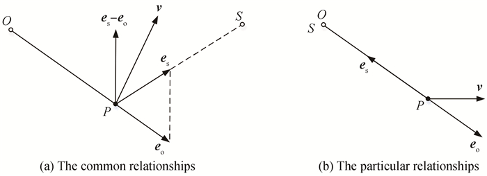
When the laser source and the photodetector are packaged together, the relative positions of the components in Fig. 1(a) can be shown as Fig. 1(b), and
![]()
Figure 1.Relative positions of light source, moving particle and light detector
According to Eq.(3), if the angle between the direction of the vehicle's velocity and the direction of the light is θ, the Doppler frequency can be given by
Therefore, the velocity of the vehicle can be given by
Because the beam output by the laser velocimeter is Gaussian beam and it has a certain divergence angle, the spot diameter at middle and long distance of the decameter range becomes larger which causes the echo signal to be very weak and the system can not work normally. The light field distribution of Gaussian beam is shown as Fig. 2(a), where ω(z) is the radius of the spot at the coordinate z, ω0 is the radius of the waist spot of the laser beam, and θ0 is the divergence angle of the far field.
![]()
Figure 2.Gaussian beam field distribution and its transmission trough a single lens
In order to enhance the echo signal and improve the signal-to-noise ratio of the Doppler signal, so the Laser speedometer can work with long distance. The Gaussian beam emitted from the system is transformed by one lens group in this paper[
where F is the focal length of the lens, ω0 is the radius of waist spot of the incident Gaussian beam, l is the distance between the waist spot and the lens, q0 is the parameter q at the waist of the incident Gaussian beam, qB is the parameter q of the Gaussian beam at the exit surface of the lens, q′0 is the parameter q at the waist of the exit Gaussian beam, ω′0 is the radius of the waist of the Gaussian beam and l′ is the distance between the waist and the lens.
Considering that it is difficult for a single lens to focus the laser beam to a long distance (decameter level), we use a short-focus concave lens and a long-focus convex lens to form a telescope-like system, and transform the Gaussian beam based on the system, as shown in Fig. 3.
![]()
Figure 3.Diagram of beam transformation of double-lens telescopic system
1.2 Optical
structure of laser velocimeter for overspeed detection The optical structure of the velocity measuring system is shown in Fig. 4. The beam emitted by the laser is divided into two beams with equal intensity by the beam splitter. The reflected beam returns in the original direction through the mirror and the attenuator, and then enters the avalanche diode through the beam splitter, polaroid, filter and diaphragm, which is the reference light; te transmitted beam passes through the beam conversion lens group and gets to the side of the vehicle. At this time, there are scattered lights in all directions. Among them, the scattered beams return in the original direction are converted by the lens group again. And similarly they get to the avalanche diode through the beam splitter, polaroid, filter, and diaphragm, which is the signal light. There are two main functions of the beam conversion lens group here: the first one is to change the beam waist of the laser to the far lane; the second one is to receive the echo signal. The reference light and the signal light interfere with each other on the photosensitive surface of the avalanche diode, and the voltage signal output by the avalanche diode module contains the Doppler signal with the Doppler frequency because of the square rate effect of the photodetector. The subsequent circuit can process the Doppler signal and extract the Doppler frequency, and then the velocity can be calculated.
![]()
Figure 4.Structure of the laser velocity measuring system
As for the signal processing method, Fast Fourier Transform (FFT) is used, mainly because this method has a strong ability to extract signals from noise and can accept discontinuous signals.The flow chart of signal processing is shown in Fig. 5. After the avalanche diode module converts the optical signal into the electrical signal, the data acquisition card completes the signal acquisition and transmits it to the PC. The original signal is first high-pass filtered to remove the base signal in the LabVIEW platform. Then, the FFT is performed on the filtered signal to obtain its frequency spectrum. The frequency spectrum refinement algorithm and correction technique are used to refine and correct the frequency spectrum of the signal[
![]()
Figure 5.The flow chart of signal processing
2 Experiments and analysis
According to Fig. 4, the optical path is adjusted, and a laser velocity measuring system is designed. The main technical parameters of the system are shown in Table 1.
| Parameter | Value | |
| Wavelength/nm | 532 | |
| Laser | Power/mW | 50 |
| mode | Single longitudinal | |
| Focal length of concave lens/mm | -35 | |
| Beam conversion lens group | Focal length of convex lens/mm | 500 |
| Distance between lenses/mm | 335 | |
| Photodetector | APD | |
| Beam angle/(°) | 75 | |
| Signal processing algorithm | FFT | |
| Central working distance/m | 10 | |
| Measurement accuracy/% | < 0.1 | |
| Resolution/(m·s-1) | 0.01 | |
| Measuring range/(km·h-1) | 0~200 | |
Table 1. Main technical parameters of laser velocimeter
The central working distance of the system is 10 m, and the measuring depth of field is 2 m. The results of measuring the spot diameters within the working distance by a spot analyzer are as follows:the spot diameter at the beam waist is 1.28 mm (Fig. 6), and the spot diameters at 9 m and 11 m from the system are 1.31 mm and 1.35 mm respectively. It can be seen that the lens group convert Gaussian beam very well, and the spot diameters within the target working distance are less than 1.5 mm, which enables the system to collect strong echo signal.
![]()
Figure 6.Two-dimensional image of the spot at the central working distance
Before the actual velocity measurement test on the road, the precision evaluation experiment of the laser velocimeter was implemented using a turntable of the Provincial Institute of Metrology. The rotational speed of this turntable is very stable and the accuracy is good to 3×10⁻⁵, so the speed of the turntable can be regarded as the reference value. Since the actual velocity of vehicles on the road can not meet the test conditions of low speed to high speed changes ideally, in order to verify that the laser velocimeter can still guarantee a certain accuracy when it works under different velocity conditions, the speed of the turntable is set to 20 km/h, 80 km/h and 200 km/h respectively. The accuracy evaluation experiment was carried out, and the experimental results are shown in Table 2. Therefore, the measuring accuracy of the laser velocimeter in this paper is good to 10-3, and the measuring range can meet 0~200 km/h.
| Speed level/(km·h-1) | Serial number | Turntable/(km·h-1) | Laser velocimeter/(km·h-1) | Accuracy/% |
| 20 | 1 | 20.053 221 | 20.042 6 | -0.053 |
| 2 | 20.053 357 | 20.046 9 | -0.032 | |
| 3 | 20.053 293 | 20.055 5 | 0.011 | |
| 4 | 20.053 221 | 20.038 2 | -0.075 | |
| 5 | 20.053 150 | 20.059 8 | 0.033 | |
| 6 | 20.053 007 | 20.051 2 | -0.009 | |
| 80 | 1 | 80.152 359 | 80.140 3 | -0.015 |
| 2 | 80.152 428 | 80.170 8 | 0.023 | |
| 3 | 80.152 466 | 80.174 3 | 0.027 | |
| 4 | 80.152 496 | 80.139 1 | -0.017 | |
| 5 | 80.152 466 | 80.108 3 | -0.055 | |
| 6 | 80.152 390 | 80.140 8 | -0.014 | |
| 200 | 1 | 200.227 173 | 200.124 0 | -0.052 |
| 2 | 200.227 249 | 200.428 0 | 0.100 | |
| 3 | 200.227 463 | 200.276 0 | 0.024 | |
| 4 | 200.227 737 | 200.233 0 | 0.003 | |
| 5 | 200.228 104 | 200.233 0 | 0.002 | |
| 6 | 200.228 348 | 200.319 0 | 0.045 |
Table 2. Experimental results atdifferent velocity levels
In particular, the working frequency of the velocimeter in this paper can reach 200 Hz (that is, the period is 5 ms). When a normal car whose length is 4 m passes the velocimeter at a high speed of 200 km/h, it takes 72 ms, which is greater than 5 ms, so the velocimeter can still work normally when the traffic volume is large.
In addition, the resolution of the velocimeter is 0.01 m/s, which is obtained by the resolution of Doppler frequency. According to the optical Doppler effect, the velocity of the measured object can be calculated from the Doppler frequency shift (Eq.(5)), so the resolution of velocity is determined by the frequency resolution, and the frequency resolution is given by
where fs is sampling frequency, N is the sampling points (analysis data length).
After the above analysis of main performance parameters, several well-known velocimeter products' parameters are listed in Table 3 in order to further demonstrate the advantages of the velocimeter in this paper.
| Brand | Maximum working distance/mm | Depth of field/mm | Measurement range/(m·min-1) |
| Elovis | 500 | ±20 | 0~3 600 |
| POLYTEC | 2 500 | ±30 | 0~7 000 |
| BETA | 3 000 | ±175 | 0~4 000 |
| Velocimeter in this paper | 10 000 | ±1 000 | 0~3 600 |
Table 3. Performance comparison of velocimeter products
As can be seen from Table 3, the working distance of the velocimeter in this paper has obvious advantages, and the measured vehicle can be allowed to move within a certain range in the longitudinal position due to the large depth of field. The measurement range can reach 0~3 600 m/min, and the corresponding maximum velocity is about 200 km/h, so it can meet the actual velocity measurement requirements on the road.
After the critical performance of the laser velocimeter has been verified, the laser velocimeter is used for actual roadside testing, which includes the experiment of the effect of the beam conversion lens group on theecho signal and the velocity test of the actual driving vehicles.
The measuring system is installed for testing by a tripod on the roadside, as shown in Fig. 7. In order to verify the effect of the beam conversion lens group to enhance the echo signal, a comparative experiment based on two systems (one system with the beam conversion lens group and another without the lens group) is carried out. At the distance of 10 m from the system, the handheld cardboard sways back and forth against the laser, and the results are shown in Fig. 8, where Fig. 8(a) and Fig. 8(c) are the voltage signals and their spectrum collected by the system without the conversion lens group; Fig. 8(b) and Fig. 8(d) are the voltage signals and their spectrum collected by the system with the conversion lens group. It can be seen from Fig. 8 that when the conversion lens group is not installed in the measuring system, the Doppler signal can not be extracted due to the noise. After the conversion lens group is installed, the echo signal is significantly enhanced, and the signal-to-noise ratio of the Doppler signal is relatively high. This is mainly because the spot radius within the working distance is greatly reduced after the conversion lens group transforms the Gaussian beam, which enhances the scattered light returning in the original path and it is received by the system. According to the spectrum of the signal, we can know that the corresponding Doppler frequency is fD=4.18 MHz.
![]()
Figure 7.Actual testing environment of the system
![]()
Figure 8.Signals of the system without the conversion lens group and the system with conversion lens group
In addition, we measure the passing vehicles' velocities by the measuring system with conversion lens group, and the result is shown in Fig. 9. Fig. 10(a)~Fig. 10(f) are enlarged views of the six peaks in Fig. 9 respectively. It can be seen from Fig. 9 and Fig. 10 that the entire test process takes less than 8 minutes and 6 vehicles passed by. The maximum velocity is 14.61 m/s and the minimum velocity is 6.93 m/s. Moreover, the time corresponding to obtain the velocity of each car is different, and the time of the first car is 0.28 s(shortest), the time of the fifth car is the 0.71 s(longest). This is mainly because the length of each car is not the same, and the velocity of each car is also different. When the body length is the same, the lower the speed when the vehicle passes, the longer it takes to obtain the vehicle's velocity.
![]()
Figure 9.Results of velocity measuring of passing vehicles
![]()
Figure 10.The enlarged views of the six peaks in
3 Conclusion
Aiming at the problem of short measuring distance of traditional laser Doppler velocimeter, a portable laser Doppler velocity measuring system with the double lens telescopic system was successfully designed based on the reference beam measuring model in this paper. The Gaussian beam after the conversion was measured and analyzed, and the actual velocity test by the developed measuring system was carried out. Finally, the velocities of passing vehicles were obtained successfully. Compared with traditional laser Doppler velocimeters, this portable laser Doppler velocity measuring system improves the center working distance and the depth of field greatly. The center working distance is 10 m, and the depth of field is ±1 m, and the velocity measurement accuracy can reach to 0.1%. Therefore, it is feasible to use this portable laser Doppler velocity measuring system for overspeed detection on highways.
References
[3] Hui-ming MA. Review of detection technology for vehicle velocity. Journal of North University of China (Natural Science Edition), 28, 139-144(2007).
[8] Yan-yan ZHANG, Ke GONG, Shu-fang HE. Progress in laser Doppler velocity measurement techniques. Laser and Infrared, 40, 1157-1162(2010).
[12] Xiong SHEN. Laser doppler velocimetry and its application(2004).

Set citation alerts for the article
Please enter your email address
© Copyright 2018-2021 | Chinese Laser Press. All Rights Reserved 沪ICP备15018463号-20