1State Key Laboratory of Modern Optical Instrumentation, Centre for Integrated Optoelectronics, College of Optical Science and Engineering, Zhejiang University, Hangzhou 310027, China
2Department of Optical Engineering, School of Opto-Electronic Engineering, Changchun University of Science and Technology, Changchun 130022, China
Yongheng Yue, Huihui Zhu, Ziwei Cao, Jianjun He, Mingyu Li. Wide-range optical sensors based on a single ring resonator with polarization multiplexing[J]. Chinese Optics Letters, 2019, 17(3): 031301
Copy Citation Text
Wide-range optical sensors based on a single ring resonator are investigated theoretically and experimentally. The sensor worked at the TE and TM modes simultaneously. Because the sensitivities of the TE mode and TM mode are different, the TE mode is used for the large measurement range, and the TM mode is used for the high sensitivity measurement. The experimental results showed that the measurement range for the TE mode was almost three times larger than that of the TM mode. A sensitivity of 233 nm/RIU was achieved for the wavelength interrogation of the TM mode.
Recent developments in the field of biosensors have heightened the need for the combination between optical technology and biosensing applications. There has been an increasing interest in investigating optical refractive index (RI) sensors with various structures, such as ring resonators[1,2], Fabry–Perot resonators[3], surface plasmon resonance (SPR)[4–6], waveguide Bragg gratings[7], a long-period fiber grating (LPFG)[8,9], and a Mach–Zehnder interferometer (MZI)[10,11]. Among them, the integrated ring resonator has been regarded as a promising solution for biosensing applications. The high- microring resonator can provide a higher sensitivity due to the sharper resonance peak. As is well known, the sensitivity is inversely proportional to measurement range for the microring sensor. However, the sensor not only needs to obtain a high sensitivity, but also a wide measurement range for the biosensing application, because the measurement range is determined by the free spectral range (FSR) of the sensing ring. To broaden the measurement range, the FSR can be increased by reducing the radius of the ring. However, the bend loss is increasing as the radius of the ring is decreasing. Extensive efforts have also been made to enlarge the measurement range by eliminating[12] or quasi-eliminating[13,14] the FSR of the ring resonator. However, the sensitivities of these sensors are not very high. In addition, there are several cascaded structures, such as a three-cascaded microring resonator[15] and an MZI-coupled microring[16], which can achieve high sensitivity and large measurement range. However, these structures are more complex than the single ring.
In this Letter, based on the traditional single ring structure, the sensor operated for both TE and TM modes simultaneously. The TM mode output signal is for the high sensitivity, while the TE mode is for the large measurement range. Experiment results showed the sensitivity of this sensor is 233 nm/refractive index unit (RIU), and the measurement range is from 0 to 0.0135 RIU for the wavelength interrogation.
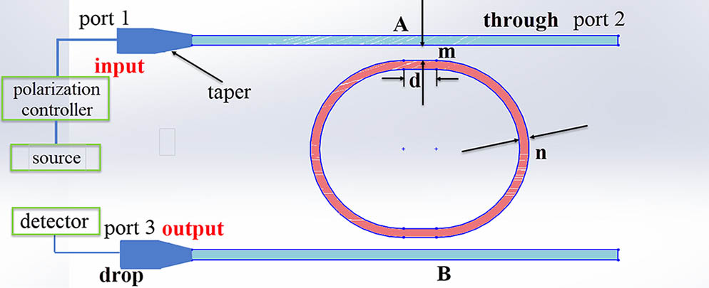
A total sensing system is shown in Fig. 1. The microring is based on the silicon-on-insulator (SOI) platform with a 220 nm thick silicon top layer and a 3 μm thick buried oxide layer. The resonant wavelength of the ring is influenced by the RI of the analyte in contact with the waveguide surface of the ring. The widths of all the straight waveguides are 0.52 μm with a ridge height of 0.22 μm, and the ring diameter is 125 μm. The width of ring () is 0.52 μm. In order to decrease the loss of coupling between the fiber and waveguide, the input and output taper waveguides are used. To achieve the wide measurement range and the high sensitivity, the TE and TM modes are propagating in the ring resonator at the same time. The coupling length () and the width of gap between the straight waveguide and ring () are set to 17 and 0.3 μm, respectively. The light from the tunable laser source (Agilent 81606 A) is coupled into the input port (port 1), and the transmitted light from drop port is received by the power detector (Agilent N7744). The polarization controller (Agilent N7788B) is used to switch the TE and TM modes.
Sign up for Chinese Optics Letters TOC. Get the latest issue of Chinese Optics Letters delivered right to you!Sign up now
Figure 1.Schematic image of the total sensing system.
The distribution of the electric field intensity of the waveguide with the upper cladding of water for TM and TE modes is simulated by the finite difference eigenmode (FDE), as shown in Figs. 2(a) and 2(b). For a waveguide with a height of 220 nm and a width of 550 nm, the is 2.501 for the TE mode and 1.747 for the TM mode. The waveguide sensitivity , expressed by the ratio between the effective RI change and the RI change () of the analytes, is 0.5 for the TM mode input and 0.14 for the TE mode. Since the sensitivity of the conventional single ring resonator (SRR) sensor is determined by the small part of the overlapping region between the evanescent field and the analyte, the sensitivity of the SRR is limited to 443.62 nm/RIU for the TM mode and 86.76 nm/RIU for the TE mode according to Eq. (2). It means that if the sensor works at the TE and TM modes simultaneously, the spectrum of the TM mode can achieve the high sensitivity, and the spectrum of the TE mode can obtain the large measurement range.
Figure 2.(a) Electric field intensity of the waveguide for the TE mode. (b) Electric field intensity of the waveguide for the TM mode.
The wavelength interrogation sensitivity (S) and measured RI range (R) are defined as follows[17]: where is the wavelength of incident light, is the group index, is the change of effective RI, is the change of the sample RI, is the wavelength sensitivity, is the measurement range, and FSR is the free spectral range. The measurement range is inversely proportional to the sensitivity for a given FSR.
The dispersions of the effective index for the TE and TM modes were considered in the simulation. The transmission spectra of the drop port for the two polarizations are shown in Fig. 3(a), and the wavelength shifts versus RI change of the analyte are shown in Fig. 3(b). As shown in Fig. 3(a), the FSR of the TE mode is smaller than that of the TM mode because the of the TE mode is larger than that of the TM mode. From Fig. 3(b), the sensitivity of the TM mode is around 5.4 times higher than that of the TE mode, and the measurement range of the TE mode is about 3.9 times higher than that of the TM mode. The combination of the TE and TM modes can achieve the high sensitivity while increasing the measurement range.
Figure 3.(a) Simulated transmission spectra of the TE and TM modes. (b) Simulated wavelength shifts versus RI change for the TE and TM modes.
To verify the numerical simulation results, a single ring resonator was fabricated and measured. The waveguide structure was patterned by electron beam lithography and then etched by inductively coupled plasma (ICP). The scanning electron microscope (SEM) image and the optical microscope image of the microring structure are presented in Figs. 4(a) and 4(b). The whole chip is shown in Fig. 5(a), and the total measurement setup is depicted in Fig. 5(b). The microfluidic channel fabricated by polydimethylsiloxane (PDMS) is stuck on the chip as a liquid inlet and outlet.
Figure 4.(a) SEM image of the direction coupler. (b) Optical microscope image of the microring.
When NaCl solutions with different volume concentrations were injected, the transmission spectra with the TM and TE modes of the sensor are measured, as shown in Figs. 6(a) and 6(b). The factor of the fabricated resonators is around 6116 from the spectra in Fig. 6. When the concentration of NaCl (aq) changes from 0 to 1.5%, the resonance wavelength shifts from 1577.68 to 1578.32 nm for the TM mode and from 1578.09 to 1578.26 nm for the TE mode. The peak shifts of both the TM and TE modes are within their measurement range. When the concentration of aqueous solutions of NaCl changes to 3.0%, the peak shift for the TE mode is still within its measurement range, but the TM mode has exceeded its measurement range. It is obvious that the RI change cannot be measured when the concentration of NaCl (aq) changes from 0 to 3.0% for the TM mode. Based on the polarization multiplexing, the measurement range can be extended. The measured wavelength shift versus the RI change of NaCl solutions with different concentrations for TE and TM modes is further shown in Fig. 7. The sensitivity is 233 nm/RIU for the TM mode, and the measurement range of the TE mode is 2.8 times wider than that of the TM mode.
Figure 6.(a) Measured transmission spectra of the TM mode when the concentration of aqueous solutions of NaCl changes from 0 to 3%. (b) Measured transmission spectra of the TE mode when the concentration of aqueous solutions of NaCl changes from 0 to 3%.
In conclusion, a method to enlarge the measurement range of the single ring sensor is proposed theoretically and experimentally. The measured sensitivity for TM is obtained up to 233 nm/RIU, and the measurement range of the TE mode is about 2.8 times wider than that of the TM mode. The reported SOI-based microring sensors can be made as a large array for different functions, not only to detect different types of the analyte, but also to use some sensors as a reference. Therefore, this sensor possesses key merits when a large and precise RI change is required for the simple, low cost, and portable instrument.
Yongheng Yue, Huihui Zhu, Ziwei Cao, Jianjun He, Mingyu Li. Wide-range optical sensors based on a single ring resonator with polarization multiplexing[J]. Chinese Optics Letters, 2019, 17(3): 031301